Monitoring a solar installation by tapping into a SunPower PVS5 or PVS6
This documentation has seen many updates over time. Too many to list, individually, except to say that a new local monitoring API from SunStrong is now also documented.
In the past, I have made this information available in a PDF. Since I have now created this page, I will no longer update that document. However, you can get a close replica by “printing” this page to PDF!
DISCLAIMER:
Everything provided/stated in this document is the result of internet-based search results, Sunpower Documentation, and research by the author and acknowledged contributors.
NOTHING IN THIS DOCUMENT IS CONSIDERED TO BE A DEFINITIVE REFERENCE OR GUIDE, AND ANY ACTIONS YOU TAKE BASED ON THIS INFORMATION ARE YOUR OWN RESPONSIBILITY. THE SYSTEMS IN QUESTION CONTAIN CONNECTIONS FOR HIGH VOLTAGE AND HIGH POWER ELECTRONICS, AND YOU SHOULD BE AWARE OF THAT. TAKE ALL NECESSARY PRECAUTIONS FOR WORKING AROUND THOSE, INCLUDING SWITCHING OFF COMPONENTS. YOU SHOULD TAKE SAFETY MEASURES AND BE AWARE OF ASSOCIATED RISKS (INCLUDING DEATH) SHOULD YOU FAIL TO DO SO. THE AUTHOR(S) DO NOT ASSUME ANY RESPONSIBILITY OR LIABILITY! CONSULT YOUR SYSTEM DOCUMENTATION FOR ANY ADVERSE IMPACTS TO YOUR SYSTEM’S WARRANTY.
Introduction
The following describes how to set up a method for issuing HTTP commands to a SunPower PVS5 or PVS6 monitoring system. This information was gathered from several different places on the Internet, but is presented here in an attempt to provide a single comprehensive document. The most notable sources used were:
- Monitoring a SunPower Solar System (https://blog.gruby.com/2020/04/28/monitoring-a-sunpower-solar-system/)
- Describes Scott’s experience, and configuring a Raspberry Pi3, and how he uses Home Assistant with Grafana to build a dashboard
- SunPower PVS5x/PVS6 Notes (https://github.com/ginoledesma/sunpower-pvs-exporter/blob/master/sunpower_pvs_notes.md)
- Documents using a Raspberry Pi3 as a bridge to the PVS5x or PVS6 system, as well as some of the API commands (with a few errors)
- The GitHub repository also contains some code
- Sunpower PVS6 Installation Instructions (https://us.sunpower.com/sites/default/files/sunpower-pv-supervisor-6-installation-instructions-531566-reva_0.pdf). This is for the (older) model equipped with Ethernet ports.
- Sunpower PVS6 Residential Installation Instructions (https://fccid.io/YAW539848-Z/User-Manual/Users-Manual-rev-6022499.pdf). This is for the newer model (2022), which is not equipped with Ethernet ports but does have USB ports that accept certain dongles.
- https://us.sunpower.com/sites/default/files/sunpower-pvs5x-install-and-quick-start-guide-522351_0.pdf
- Commissioning EquinoxTM Systems using WiFi (https://us.sunpower.com/sites/default/files/tech-note-commissioning-equinoxtm-systems-using-wifi-534241-004_0.pdf)
- Equinox Installation Support (https://us.sunpower.com/support/install/equinox)
- Conext XW Pro Hybrid Inverter (https://www.se.com/ww/en/product-range/66297-conext-xw-pro/?parent-subcategory-id=7010&filter=business-7-solar-and-energy-storage#overview)
- Conext Battery Monitor (https://www.se.com/ww/en/product-range/65504-conext-battery-monitor/?parent-subcategory-id=7040&filter=business-7-solar-and-energy-storage#overview)
- Conext Gateway (https://solar.se.com/us/en/product/conext-gateway/). This is listed as a discontinued product, but may still contain information relevant to its replacement.
- Thanks to Dean Ott, who confirmed to me that he has all this working with a PVS5 system (he uses two cables: one for outbound access for the PVS5 (instead of WiFi), and one to a Raspberry Pi) inside his wiring closet.
- Thanks to Phill West, who owns a system with a SunVault ESS battery system.
The basic reason for even wanting to bother with all this is the finding that the SunPower mobile app or website that is offered to customers is extremely limited in functionality. It only offers insights into current solar production, current consumption (only if a metering kit was installed, which oftentimes is not the case, so you would have to ask for it), and some historical graphs showing kWh produced or power output. There is no information about the functional state of individual system components, nor are there detailed performance metrics. Additionally, it appears that the SunPower data on the app or website may be updated only in near real time.
Using the approach described here, more detailed data and higher-frequency data are available. I first describe the basic functioning of the PVS system and how one can “tap” into it, then discuss the specific solution using a Raspberry Pi 3 (and later, a Pi Zero W). Finally, I document the API that becomes available using this approach. The API can be used by custom code you or somebody else writes. One such example is an integration called SunPower for Home Assistant (https://github.com/krbaker/hass-sunpower). A second, and more modern is Enhanced SunPower.
New Sunstrong-related information (11/10/25)
Ever since the SunPower bankruptcy and the subsequent acquisition of some assets by SunStrong, there has been uncertainty about how long the approaches described here would remain valid. In particular, because the newer SunStrong application is more limited unless you pay for a subscription, and because it was unknown whether SunStrong would perhaps change the firmware to block the kind of monitoring described here.
I discovered a few weeks ago that things have, indeed, changed. As I write this, my PVS6 is (still) on firmware version 2025.06, but others have reported newer versions. Along with that came reports of monitoring via the commands described here, encountering 403 (Not Authorized) errors.
Some research uncovered what happened:
- Sunstrong introduced a new API for local monitoring that became available in versions after 2025.06
- This new API requires an authentication step before the API can be used
- The old API still works, but…
- Perhaps inadvertently, the old API (which runs on the same web server as the new one) now also requires that same authentication step.
Below, I will provide information about the new API and the authentication method that works with both the old and new APIs. I will also point to available plugins for Homeassistant the should allow you to work with old or new APIs.
The new local monitoring API
Sunstrong implemented a new local monitoring API on top of a facility they introduced a while ago, called “var server”. VarServer is a basic key/value store, and, using this new API, it can be interrogated to obtain various telemetry values. Sunstrong has documented VarServer and the new API and has also created a Python library for interacting with it.
It should also be noted that the PVS will now listen for these API requests on the PVS6’s IP address on your local network. In other words, to access this API, you no longer need any of the solutions described here using a Raspberry Pi or equivalent. I have not been able to test this myself as I am still on old firmware. That said, proxying through the Pi should also still work.
While this new API and the fact that a Raspberry Pi is no longer needed might make things a lot simpler, you might still want to look through the rest of this document to learn more specific information. Unless you will only be using a Homeassistant plugin, that information might still come in very handy.
This new API is officially documented. The “old” one was never officially documented, although a fair amount of unofficial documentation can be found in this document.
The new API is documented in the open-source and public GitHub repository created by SunStrong. Another file states which parts of the legacy dl_cgi interface are still supported, but also makes it clear that:
- Authentication is now required
- This API should really not be used anymore
- This API may disappear
Two more files describe the VarServer endpoints that are available for PVS5 and PVS6:
The PyPVS Python library is documented on GitHub, and the source code can be found in that repository, along with examples.
Authentication
Authentication is now required for most of the still-supported old API and much of the new one. The basic method requires you to know the last five characters of your device’s serial number.
NOTE: If your firmware is newer than 2025.06, this means that without modified software in Homeassistant or whatever other solution you may have been using, things will now fail with a 403 error!
Details can also be found in the main documentation, but it boils down to the following steps:
- Form a string concatenating the text “ssm_owner”, a colon, and the last five characters of your serial number.
- Put that string in base64 encoded format
- Make a GET request to the endpoint
https://<ip address>/auth?loginwhile providing a header with the request “Authorization: basic $auth” where$authis the base64 encoded string from above. - The response will now include a cookie named
sessionthat must be included in all subsequent API requests.
Swagger (old API)
Since writing this document, I have found that one can now obtain a Swagger file for the “old” api.
A Swagger file, now formally known as an OpenAPI Specification (OAS) file, is a language-agnostic, machine-readable, and human-readable description of a RESTful API. It serves as a blueprint or contract for your API, detailing its functionality and how to interact with it.
The file can be downloaded using the URL http://<your PVS6 IP address on WiFi>cgi-bin/swagger.json (if you have followed instructions here). You can then read it for more information or import it into OpenAPI-compatible tools, such as RapidAPI. These tools will enable quick experimentation with the API.
If you are on old(er) firmware, you will still need the Raspberry Pi, and you will need to use the Raspberry Pi’s IP address instead!
Homeassistant integration
I don’t know if the “original” Homeassistant integration from “krbaker” works with the new authorization, but the old API, or not (could not test). However, I found two other integrations that appear to do the job.
- The first one is published by SunStrong and uses the new Python library and, as far as I can tell, will only work if you have the newer firmware: https://github.com/SunStrong-Management/pvs-hass
- The second one claims to work, universally and transparently, with both old and new APIs. It even handles the old API without authentication needs, as well: https://github.com/smcneece/ha-esunpower. This is the one I currently use (with new firmware).
Other Resources
If you would like to do some more “manual” experimentation, I have the following resources:
- Use a program such as RapidAPI, or equivalent, perhaps even curl (more manual and more involved, but it works nonetheless).
- Use this shell script, or modifications of it: https://gist.github.com/koleson/d54e0cd1f3bce3aedf13be005df99abb
The PVS6 system
What follows may not precisely describe how things are for the PVS5 series. Although it seems very similar in terms of the functionality described here, I don’t have one, so I couldn’t test it (but I have confirmation that things work basically the same). The system is a separate box (except in ESS-based installations), typically installed near the (sub)panel where the wiring from the solar array is hooked up. Inside it generally contains connections to one or two circular magnets/coils, called a Current Transformer (CT) that are installed around the PVS wires so that the energy produced can be monitored. There may also be a set installed around the incoming utility wires (a so-called metering kit). The latter is often omitted unless you have battery storage, in which case it is needed to properly decide where to route energy produced by the PV system (i.e., to the battery and/or the grid). The system will be powered via its private breaker circuit.
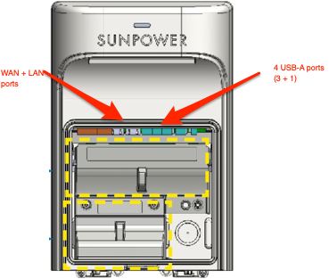
The system has several I/O ports inside (remove the front cover). Most notably, there are two Ethernet ports labeled WAN/LAN2 and LAN1, and 4 USB-A ports. Also available is a wireless radio (for WiFi access) and a cellular system, which will most of the time not be equipped with a SIM unless you have cellular as your only option for connecting to the Internet for monitoring and uploading to SunPower. Finally, there is also a facility to access the PVS monitoring system through PLC (Power Line Communication). The latter is also how the monitoring system communicates with all the microinverters for the panels. The USB ports do not appear to be in use and are probably part of a fairly generic motherboard used inside. They can come in handy, though, as you will see later.
In the most basic setup, the PVS monitoring system needs Internet access to communicate with SunPower’s cloud. In many, if not most, customer installations, this is achieved by connecting to the customer’s WiFi network. Where this is not possible or not desirable, an Ethernet cable from the WAN port to the customer network is another option (but often cumbersome, as the panel will likely be outside, so a cable will have to be routed to a suitable location inside). In both cases, the PVS monitoring system will act as a DHCP client on the customer network to obtain its IP address; however, it is also possible to configure a static IP address using installer access via the specialized mobile app. Generally, it is advisable to leave things as DHCP, but configure your home router or WiFi with a statically reserved DHCP address so the box always gets the same IP address. If the above two solutions fail, a PLC-based connection is the next option; finally, there is cellular. Only the latter will prevent the PVS monitoring system from being available on the customer network, and everything discussed here cannot be used.
While the WAN port is for wired communication between the PVS monitoring system and the customer network, the LAN port is intended for the system installer. A laptop can be plugged into it directly. To support this mode of operation, the PVS monitoring system runs a DHCP server on this port, so the laptop can obtain a suitable IP address, routing information (the PVS monitoring system is the gateway), and DNS (so that a lookup of www.sunpowerconsole.com will work). The port presents a network with address 172.27.153.0/24 (netmask 255.255.255.0), and the PVS monitoring system will be at the gateway address supplied by DHCP (this seems to always be 172.27.153.1). The laptop will get a suitable address on the same network.
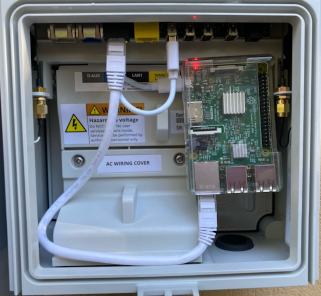
The black port is LAN1, and the yellow port is WAN/LAN2! Raspberry powered from USB port 1. Using short cables, plenty of space.
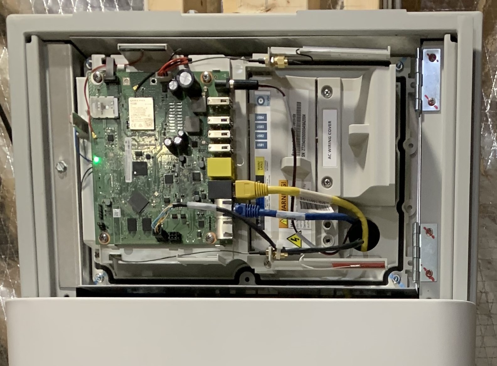
NOTE: I have reports of a newer version of the PVS6 being used. This newer version lacks the two ethernet ports. Its insides look like this: 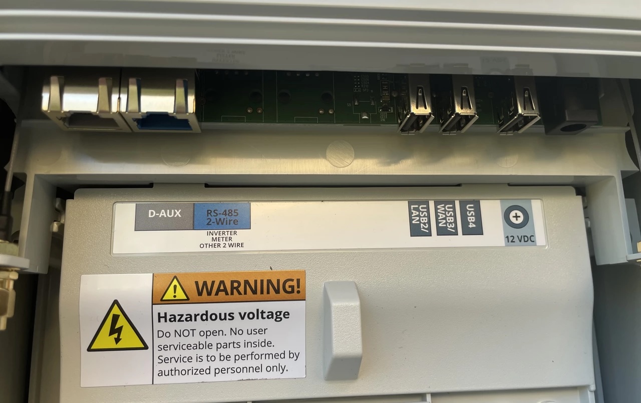
Note that the traditional ethernet ports are no longer there, but there are two USB ports that are also labeled LAN and WAN respectively. Of course, USB does not equal ethernet so the suspicion is that the USB ports can accept ethernet adapters, but so far those that have tried to use ethernet this way have not been successful.
NOTE: It seems that the ports will indeed take USB Ethernet adapters, but only certain brands/models will work.
The above picture is from the standalone PVS6, a newer version, without Ethernet ports. Here is a picture inside the “modern” ESS installation of the same PVS6, but exposing more of the inside:
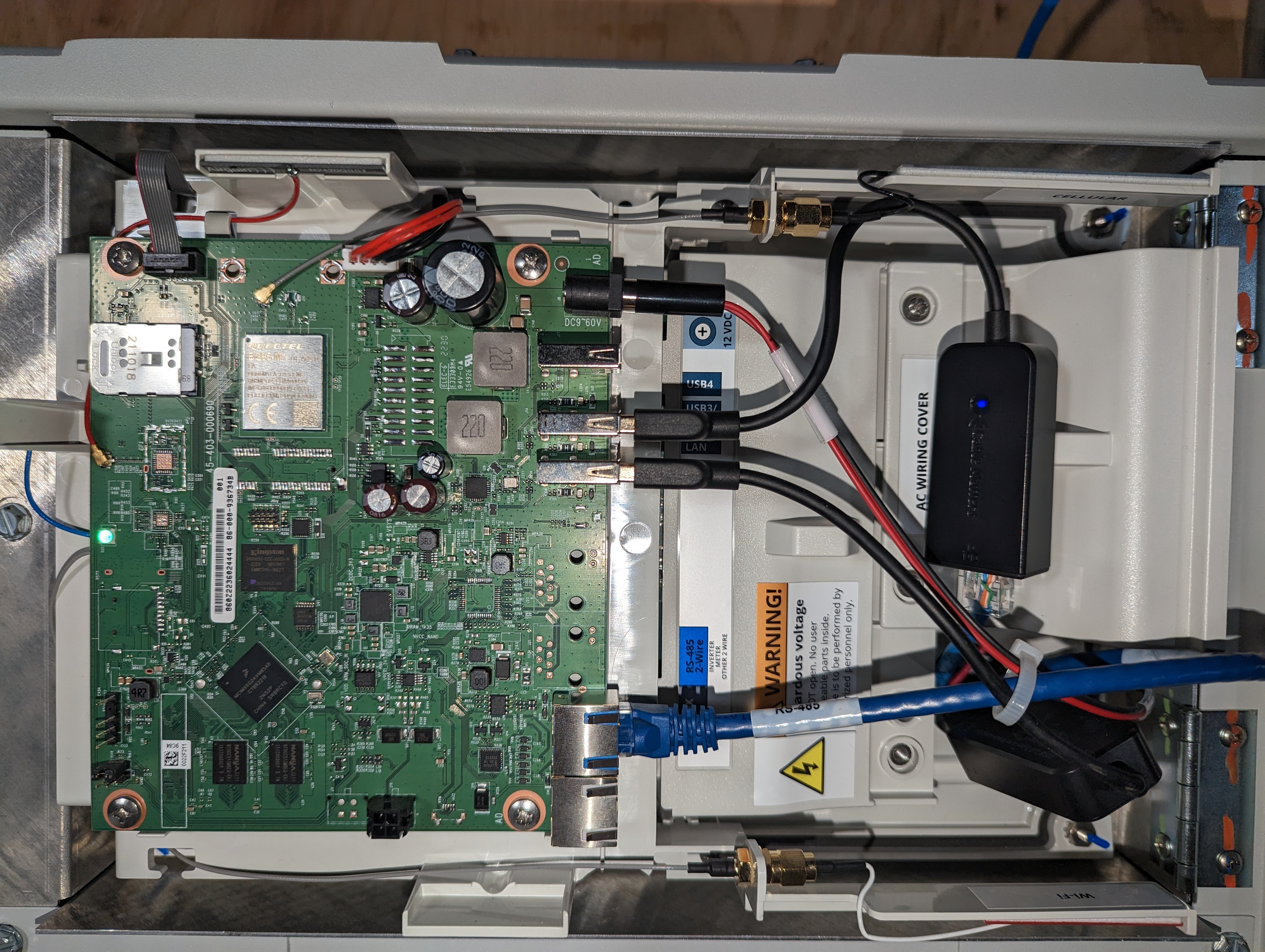
Visible here on the right side of the green PCS, from top to bottom (corresponding with right to left in the picture above it):
- Power adapter port
- USB port (nothhing plugged in here)
- USB port with Ethernet dongle plugged in (ostensibly for WAN/Internet access). This one is optional
- USB port with what appears to be a second dongle plugged in (for connection to the ESS Gateway). This one is required
- RS-485 cable (looks like Ethernet, but it is not Ethernet) for serial communication with Inverters and ESS sub systems
- D-AUX port, nothing plugged in
The laptop tapping into this port is the legacy way of configuring the system. These days installers can use a mobile app available from the iOS app store, and I assume there is also an Android version. The app initially uses BlueTooth to connect. It will obtain the name of a WiFi network presented by the system and subsequently, your mobile device will need to be configured to connect to that network to access the needed functionality. While you can download this app yourself, soon after you start it it requires you to login to the SunPower portal with a qualified installer account. An account that they presumably will not give to an end user.
I also found a https://us.sunpower.com/sites/default/files/tech-note-commissioning-equinoxtm-systems-using-wifi-534241-004_0.pdf (from August 2019) detailing how to connect to the PVS6 using laptop and WiFi. Apparently during commisioning the box provides a WiFi network. Using the serial number found on a sticker(s) on the box, numbering its characters from left to right, starting at 1 (we’ll use sample ZT190585000549A6185):
- Characters 5, 6, followed by last 3 characters appended to “SunPower” will be the SSID to connect to (Example: `SunPower0518)
- Characters 3, 4, 5, 6 followed by last four characters will be the password to use (Example:
19056185)
This WiFi network is apparently available for four hours after power up unless commisioning is complete. If commisioning is started in that window, it will stay active. If you go beyond the window, you can reboot (power cycle) the PVS6 and a new 4 hour window will start.
NOTE: It appears that, at least in early 2024 on my PVS6, this network is no longer deactivated after 4 hours. This is likely to provide mobile phone access for installers without requiring them to power cycle the PVS system.
The way the LAN port works is that the monitoring system runs a web server, which listens on port 80 (standard http port) and 443 (standard SSL port). If one accesses www.sunpowerconsole.com from a browser on the laptop you will see something like this:
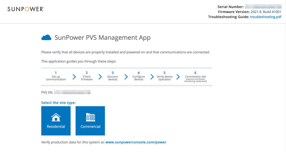
Unless you can see this, something is wrong with your setup! Other urls available:
- http://www.sunpowerconsole.com/#/summary: leads to (step 5 of 6) summary of status page
- http://www.sunpowerconsole.com/#/landing: leads to the landing page
- http://www.sunpowerconsole.com/#/firmware: checks for an applies firmware update
- http://www.sunpowerconsole.com/#/network/config: leads to network setup page
- http://www.sunpowerconsole.com/#/rma-device-selection: allows request equipment RMA
- http://www.sunpowerconsole.com/#/devices/inverter-micro: returns mostly empty results for me with callback errors to “https://pvsmgmt.us.sunpower.com/”
NOTE: I don’t know when this changed exactly, but I suspect somewhere in the second half of 2023, these URLs no longer work. They all return a “403 Forbidden” response in newer firmware versions. This is likely coincident with the notion that SuUnpower does not want installers to use a laptop anymore, but rather use the “SunPower Pro Connect” phone application. For this purpose also, the PVS system seems to now always have its WiFi network on (meaning its management WiFi network).
Now, you could stand out there, with your laptop, and play with this console or issue API commands, but it is not very practical beyond some basic testing. So, how to proceed? You want to create a situation where you can directly access this port from within your network. If you are connected via WiFi you are, effectively, talking to the WAN port, where neither console nor API is available. So, somehow you must connect to the LAN port. Forgetting the inconvenience (to some) of installing a cable, you can use a cable, but there are some problems you will need to get around. You cannot just plug this cable into a switch on your network as the PVS monitoring system has its own address and runs a DHCP server. You probably already have one, and chaos with networking problems will ensue. It is possible to get around this by using a dedicated port on your router or switch and configuring proper routing from your network to this network (possibly involving VLAN solutions). Since your computer stays on your network, nobody will be using the PVS-supplied DHCP server and you should be fine. You will have to make assumptions about network addresses and setup, and you will not have DNS to resolve sunpowerconsole.com for you. There are workarounds to all of this, but I consider them out of scope for this write-up.
There is another solution that is relatively cheap and easy (as described in this paragraph it does not apply to installations with a SunVault ESS). Use a very small form factor computer with at least one ethernet port and with WiFi and install it inside or near the PVS monitoring box. Ethernet connects to the PVS LAN1 port, and WiFi needs to be configured to connect to your WiFi. With some proper configuration that computer can act as a proxy between both networks. The address of that little box on your WiFi becomes, effectively the http access to the PVS system. Any HTTP query sent to the little box is forwarded to the LAN port, and any responses are forwarded back to whoever asked. A very commonly suggested solution involves a Raspberry Pi3. Principally because it is small, cheap, and comes with Ethernet and WiFi. Older models Raspberry can be equipped with a USB-based WiFi dongle fairly cheaply too, so if you have one of those lying around it can also be made to work. In the remainder, I will describe the Raspberry-based solution, but the principles should apply to almost any other small computer.
There are reports from one user with a Raspberry Pi model 4 who experienced intermittent problems due to the USB port not providing enough power. It is probably best to stay with a less power-hungry model. Very little is required from the “proxy computer,” so even the smallest Raspberry Pi Zero will work. There are also reports of some USB Ethernet adapters not working. I have only tested with the one mentioned here. That one works for me, and at least one of the users with problems reported that after switching to this adapter, things worked.
In this setup, the small computer acts as a bridge (or proxy) to the PVS6 internal network (RPi = Raspberry, and [] denotes the network interface):
sequenceDiagram
  User [Browser?]->>RPi [WiFi]: http call
  RPi [WiFi]->>RPi [Eth]: pass it on
  RPi [Eth]->>PVS6 [LAN1]: same http call
  PVS6 [LAN1]-->>RPi [Eth]: http response (json)
  RPi [Eth]->>RPi [WiFi]: pass it back
  RPi [WiFi]-->>User [Browser?]: http response (json)
The following ports/interfaces will be in use:
- PVS6 LAN1: Installer/Console port, represented with IP address:
172.27.153.1 - PVS6 WAN/LAN2: Customer/WAN port using WiFi (IP address assigned by your WiFi network and used for uploading to SunPower, not otherwise relevant in this document)
- RPi LAN1: Ethernet port, directly connected too PVS6 LAN1. Will receive an IP address from the PVS6 system in the network
172.27.153.0/24. - RPi LAN2/WiFi: Raspberry customer-facing interface. This is where you will browse to, or execute API commands. IP address assigned by customer WiFi (static reservation?)
PVS6 with SunVault battery system (ESS)
If you have a SunPower setup with SunVault Energy Storage System (ESS), you will generally have these two large boxes/cabinets:
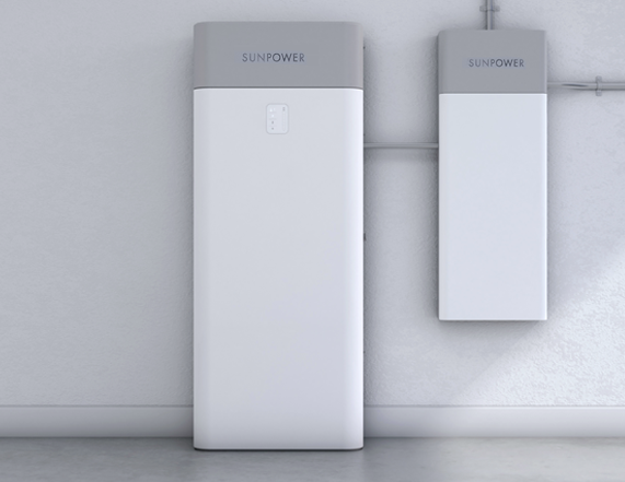
The one on the right is the HUB+, and the one on the left is a battery cabinet. Depending on your battery storage capacity, you may have more than one of these. Each cabinet contains two batteries and an inverter.
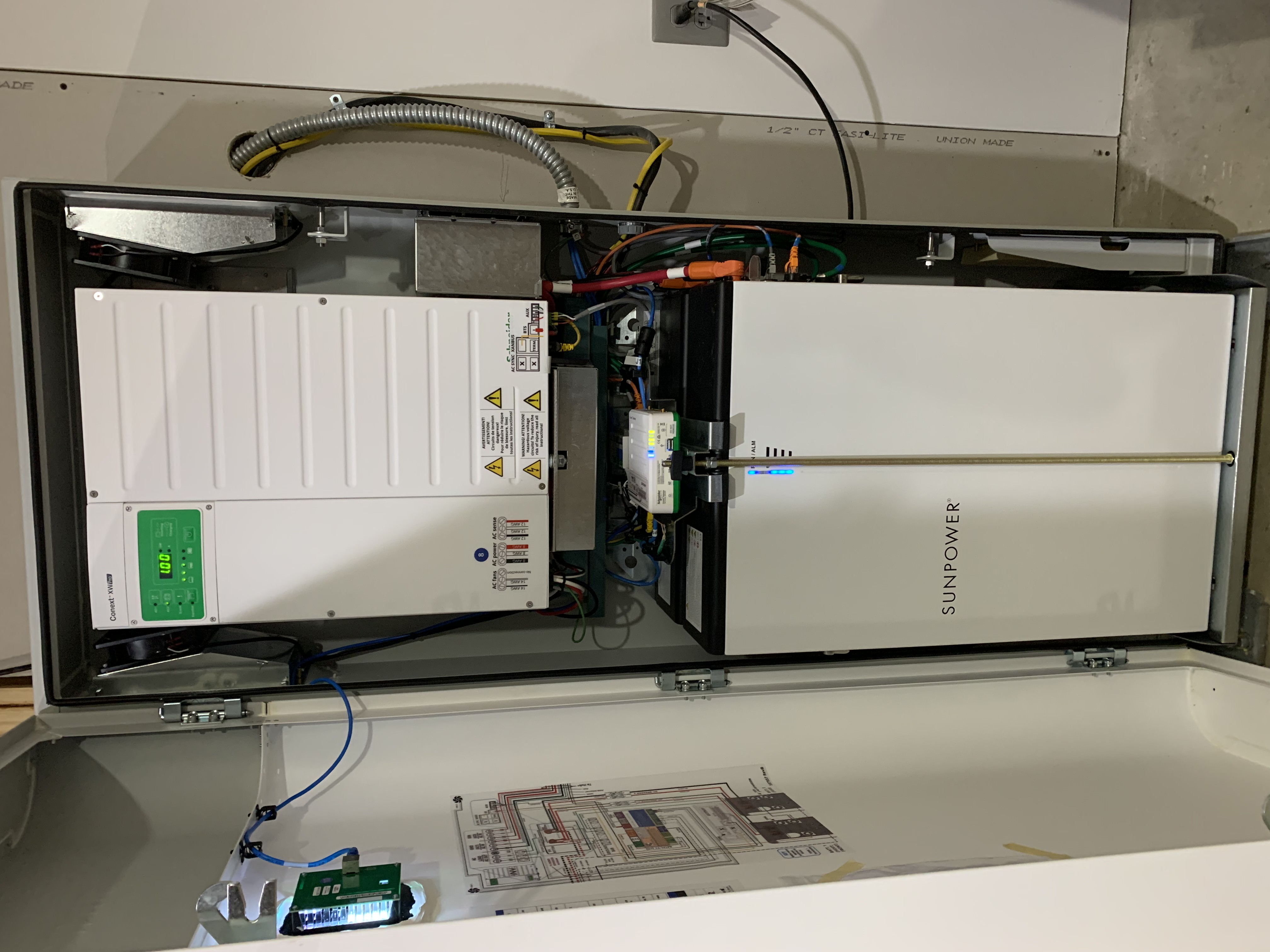
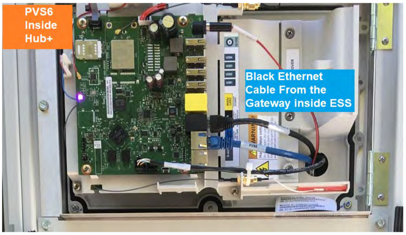
This is the HUB+ with the top panel removed (basically what you see here is the inside circuitry of the stand-alone version of the PVS6):
This is the inside of the main battery cabinet. The light-colored module in the top half is the inverter; below are two batteries. The small-ish light-colored box on top of those is the Conext Gateway device.
Inside the HUB+, you will find the following components:
- Sub-panel for backed-up loads. This will have to be wired to all circuits on the premises you desire to be backed up by battery power in the event of a utility power outage. This is the top section labeled “BACKUP LOAD PAN”.
- Sub-panel for the PV system. Typically connects both phases of the PV system and the PVS6 monitoring module. This is the middle section labeled “GENERATION PAN”.
- Sub-panel for the non-backed-up loads. This is the bottom section, labeled “NON-BACKUP LOAD PAN”.
- Microgrid interconnect device. This is a screwdriver-operated rotation switch to completely disconnect the microgrid (your PV system plus batteries) from the rest of the electrical installation
- PVS6. This is the same monitoring system mentioned elsewhere in this document. The ESS-based solution does not have its own PVS cabinet, but rather its printed circuit board is integrated with the HUB+ behind a removable panel on the top. You will need to remove/open this panel to access network connections.
The PVS6 still performs all functions and is the entity to communicate with the SunPower portal, but we do need to change the networking approach a little to make the rest of what we describe possible.
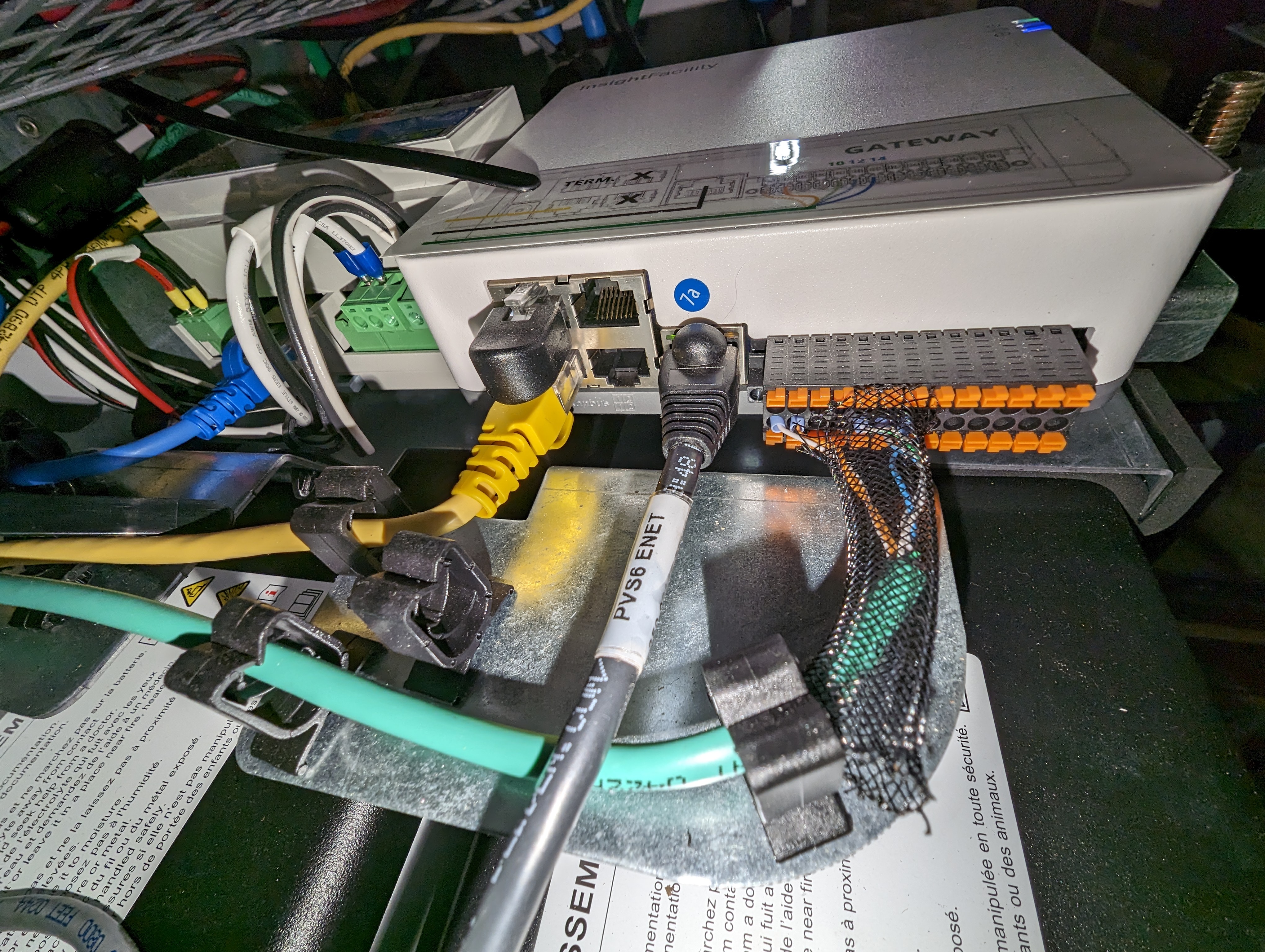
In this picture, the black cable is in the LAN1 port and it goes to the Conext Gateway device located inside the battery cabinet. The two metal-colored connectors below it (the top one of which contains the blue cable) are for RS-485 serial communications (labeled in blue with “RS-485 2-wire”, and in white with “INVERTER METER OTHER 2 WIRE”). This is the “modbus” communication system referred to elsewhere in this document. The blue cable connects the PVS6, via this serial communications channel, with the first inverter (inside your first, and perhaps only) battery cabinet. If you have more than one such cabinet there should be an additional cable from the second port in the first cabinet to the next battery cabinet. The RS-485 serial communications system is a daisy-chained channel/bus.
In some other installations the blue cable may not be used, but the black one (or perhaps other color) runs to the inverter. In this case ethernet communications is used between all devices. The instructions that follow (i.e. installing a switch etc.) don’t change, except that you could possibly leave out the switch by utilizing the unused ethernet port in the last inverter in your setup. I have not seen this myself, but documentation suggests that each inverter has two ethernet interfaces for this purpose. Overall you might be best off following a path that changes the least in your installation (which I suggest is the switch based installation).
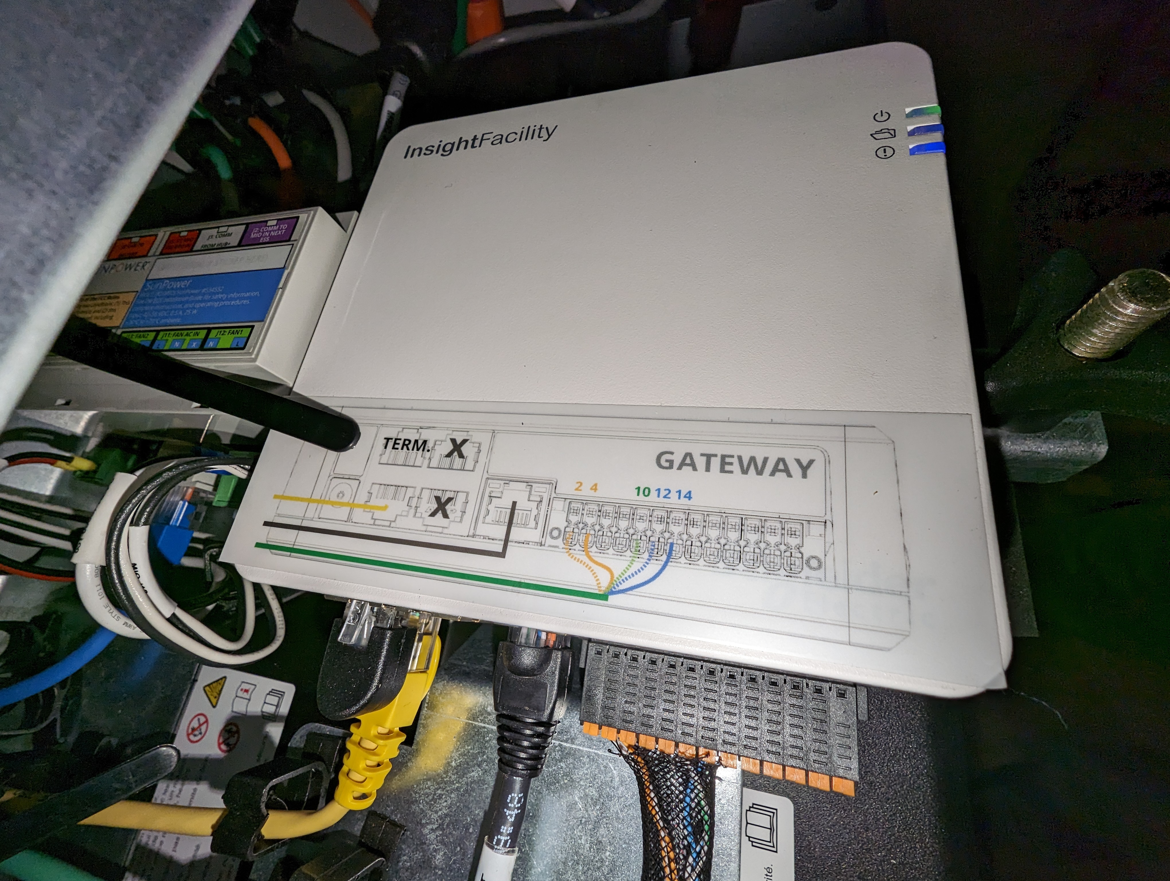
Here are some more pictures of the insides of a more receent ESS setup using the non-Ethernet PVS6 version:
 The networking setup now will require a switch (anything simple and unmanaged will do). This switch needs a minimum of 3 ports:
- This will be cabled to the PVS6 LAN 1 port and replaces the black cable in the picture
- This will be cabled to the ESS box and you can use the original black cable removed from the LAN1 port for this.
- This will be the port to connect the Raspberry to, or a laptop for testing, or a cabled solution to your home network (requires a router with an “extra” port). Alternatively an unused ethernet port in the battery cabinet on the inverter.
After placing cables (1) and (2) the PVS6 needs to “reset” its networking. This can be accomplished by rebooting the PVS or possibly by power cycling the switch. In a non-ESS setup, you can reboot the PVS6 by using the breaker to power cycle it. In a non-ESS setup power cycling using the breaker has been tested and works. In a SunVault ESS-equipped system there is a breaker, but I am not sure if cycling it is a good idea (and it has not been tested). Instead, you could remove power from the switch, wait 5 seconds, and re-establish the power. This will not do the same as a power cycle/reboot, but it will cycle the network connections and may well do the job.
Another report says a power-cycle is possible for ESS systems by both unpluggin the DC plug power from the PVS6 and by cycling the breaker in the HUB+.
After this you want to use your SunPower app to confirm the system is still reporting to their portal normally (this may take a few minutes though).
Once you decide what to plug into the third port (Raspberry approach or cabled approach), you can proceed with the instructions below substituting plugging your Raspberry’s network cable, or your cable to your home network into the third (or any) port of the switch instead of the PVS6 LAN1 port. Everything else remains the same.
Another individual has made available source code for these ESS-equipped installations that will allow monitoring of the ESS system state and battery information. It does this by “snooping” on the modbus messages, intercepting the relevant ones, and publishing messages to an MQTT broker. Solutions such as Homeassistent can then interface with the broker to get the information and do something useful with it, such as logging in to a database, displaying graphs, etc.
Setting up the Raspberry
For hardware you will need:
- Raspberry Pi3, preferably in a small enclosure. I mention this model because it has built-in WiFi and an Ethernet port. Other models may well be used for this function as well. For example the Pi Zero 2 W, at US $15, combined with an Ethernet dongle for another US $15 or so may well do the job. The Zero 2 W has the same processor as the Pi3, but less memory. After experimenting with the Pi3 successfully, I opted for this solution (Pi Zero 2 W) in the end because it is more compact, uses less power from the PVS6, and generates less heat. Ultimately, I repeated the replacement with a Raspberry Pi Zero W, which is even cheaper and has lower power demands. Part list:
- Raspberry Pi Zero W, from vilros.com
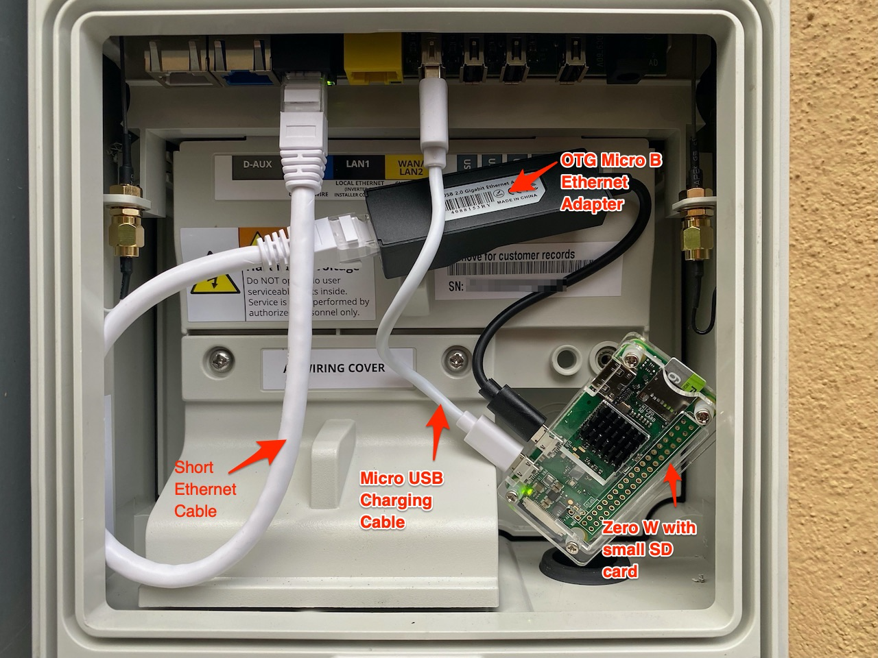
- OTG Micro B Ethernet Adapter for Linux Raspberry Pi Zero W, Windows 10 Tablet from amazon.com
- Cat6 Ethernet Cable 0.6 Feet from amazon.com
- One of Micro USB Charging Cable, CableCreation 6-Pack(0.5/0.5/4/4/6/6ft) High Speed USB to Micro USB Charging Cord (I used the 0.5 ft version) from amazon.com
- A power supply ending in a micro USB-B connector. Usually, you buy this with your Raspberry. You can also use a USB-A to micro USB-B cable with the A end plugged into a suitably equipped USB port (must be able to provide enough power, often 700mA is enough for Pi 3, or < 500 mA for Pi Zero W). Frankly, for a permanent installation, you will need the latter anyway.
- A micro SD card to load the software on. It seems an 8GB card is enough, may be even a 4GB. In my final (for now) install I used a Pi Zero W, which has only 1.4G used on its file system.
- A (short) ethernet cable to connect the Raspberry to the PVS monitoring system
This is what my final installation looks like (not quite, I replaced the Pi Zero 2W shown here, with a Pi Zero W; same footprint, same case:
Prepare the software on the Raspberry
- Download the Raspberry Pi Imager or use balenaEtcher.
- Select the Raspbian Lite image (or any other that you like and prefer, but this is good enough). Note that for a Pi Zero W you need a 32-bit version and Raspian Lite may be your only choice (and it works just fine).
- Write the image to an SD card using the imager.
- If you used Raspberry Pi Imager your resulting SD card wil now be mounted on your system and wil be accessible there. If you used balenaEtcher use Disk Utility to mount the volume first.
- Create a file, at the root level of the SD card (it will be copied into the right place once the Raspberry boots). Call it
wpa_supplicant.conf, and give it the contents listed below. This will enable the Raspberry to connect to your WiFi. - Create an empty file named
sshat the root level also. This too will be removed after boot, but causes SSH access to be configured. - Eject the SD card from your desktop or laptop
- Install SD card in Raspberry
- Connect Raspberry Ethernet port to your network
- Boot the Raspberry by applying power to it
- While not critical, you may use the command
sudo raspy-configto change the configuration to reflect your local timezone, and locale, and edit the hostname of the system.
The wpa_supplicant.conf contents:
1
2
3
4
5
6
7
8
ctrl_interface=DIR=/var/run/wpa_supplicant GROUP=netdev
update_config=1
country=US

network={
 ssid="<Name of your WiFi>"
 psk="<Password for your WiFi>"
}
Setup networking
You will need to configure things to know the IP address for your Raspberry on your network. There will be two addresses, one on the Ethernet cable and one on the WiFi (if you set everything up correctly). The best way is to make so-called static reservations for both connections in your DHCP server (typically on your WiFi router or other router). To do this, you need the MAC addresses for the Ethernet and WiFi.
If you do not have those you have to figure them out first. There are various options to do so, and methods vary a little between Windows and Mac or Linux, although the latter two may be quite similar. I suggest looking into arp -a or using the command 192.168.1.255 or similar, depending on your network settings. Once you have found the appropriate MAC addresses you can make the static DHCP reservations. How to do that depends on your equipment and I won’t discuss it here.
If you can find the IP address for either of the two ports, you should be able to log in to the Raspberry using the username pi and password “raspberry.” If you did the SSH step above correctly, this should work. Now is a good time to change the default password to something of your liking: type passwd and follow the prompts.
Reboot the Raspberry to have it find its now reserved IP address. From now on, you should be able to use SSH with that address. You might even go one step further and set your router to “publish” a name for it for your convenience. This typically involves the DNS configuration of your router. Verify you can connect to either of the two IP addresses.
Setup networking to access the PVS6
To allow the Raspberry to be the proxy we described above:
- Login to the Raspberry and update the OS:
sudo apt-get -y update; sudo apt-get -y upgrade - Install
ha-proxy:sudo apt-get install haproxy(note: no dash in the name here!) - Modify the networking setup for the Ethernet port so that it will not configure the gateway address supplied by the PVS6 DHCP server. If you do not do this or do it incorrectly, the WiFi connection will not work. If that happens, use an Ethernet cable to log in and fix it. The change requires you to edit
/etc/dhcpcd.conf, add two lines to it, and save:interface eth0nogateway
- The step above will let the Raspberry Pi use the DHCP server inside the PVS6 to obtain an IP address on its
172.27.153.0/24network. I have observed that, at times, this address stops working and, consequently, the communication with the PVS6 through the proxy stops working. Most likely, after handing out a DHCP address and having it expire (on the Raspberry Pi), an attempt to renew it fails. To get around this, configure a static address by editing the/etc/dhcpcd.confagain to add, right after theinterface eth0line:static ip_address=172.27.153.10/24
- I have found that, occasionally, the WiFi connection may be lost (e.g. after a main house power loss WiFi does not seem to reconnect). Take the following steps to have the Raspberry attempt to reconnect when the connection is lost:
- Create a file in
/usr/local/bincalledwifi-reconnect.shwith the content shown below. - Make the file executable by issuing the command:
sudo chmod +x wifi-reconnect.sh - Create an entry in crontab to run this script regularly:
sudo crontab -eand add a line containing* * * * * /usr/local/bin/wifi-reconnect.sh >> /dev/null 2>&1 - Your home directory will contain a file named
wifi-log.txtwhere you can find reconnect information logs.
- Create a file in
- Due to the above script, I have also found that WiFi connections get “lost” with a message in
/var/log/syslogsaying “wlan0: carrier lost”. While the script attempts to solve the situation, I found that on some Raspberry systems, power saving mode is enabled, causing the problem. The fix is to add a line to/etc/rc.local(and reboot, or execute the line once manually):/sbin/iw dev wlan0 set power_save off - Next, add the content shown below to
/etc/haproxy/haproxy.cfg - Reboot the Raspberry:
sudo shutdown -r now
Content of the wifi-reconnect.sh file:
1
2
3
4
5
6
7
8
9
10
11
12
13
14
15
16
17
18
19
20
21
22
23
24
25
26
27
28
29
30
31
32
33
34
35
#!/bin/bash

echo_ssid()
{
        echo "$(/sbin/iwgetid --raw)"
}

check_wifi()
{
        sleep 5
        if [ -z "$(echo_ssid)" ]; then
            echo "`date -Is` Failed to reconnect using $1" >> "$LOG"
        fi
}

LOG="/home/dolf/wifi-log.txt"

if [ -z "$(echo_ssid)" ]; then
    echo "`date -Is` WiFi interface is down, trying to reconnect" >> "$LOG"
    if command -v /sbin/ip &> /dev/null; then
        /sbin/ip link set wlan0 down
        sleep 10
        /sbin/ip link set wlan0 up
        check_wifi /sbin/ip
    elif command -v sudo ifconfig &> /dev/null; then
        sudo ifconfig wlan0 down
        sleep 10
        sudo ifconfig wlan0 up
        check_wifi ifconfig
    else
        echo "`date -Is` Failed to reconnect: neither /sbin/ip nor ifconfig commands are available" >> "$LOG"
    fi
fi

echo 'WiFi check finished'
Content to add to /etc/haproxy/haproxy.cfg:
1
2
3
4
5
6
7
8
9
10
11
12
13
14
15
16
17
18
frontend http-in
    bind *:80
    bind *:9002
    bind *:19531
    bind *:48888
    default_backend backend_servers

backend backend_servers
    server pvs6 172.27.153.1:80
    compression algo gzip
    compression type text/html text/plain text/css application/json

listen stats
    bind *:8080
    stats enable
    stats uri /
    stats refresh 10s
    stats admin if LOCALHOST
You see bindings here for port 80, the standard web port where all API calls would go, and some additional ports. Port 19531 will provide the contents of a system log to your browser. The other two ports are for WebSocket connections, whose purpose and protocol are unknown.
Install the Raspberry inside/along the PVS6 system
Open the PVS monitoring system by releasing the clip at the front bottom. This will expose the inside where the ports are. For now, it will be most straightforward to hook everything up provisionally and worry about stashing everything away later.
Plug a (short) Ethernet cable from the Raspberry into the LAN(1) port. Provide a power source to the Raspberry:
- Use a (short) USB-A to micro B. I tested this with ports 3 and 4, but I think any of this will work. It seems to supply enough power for the Raspberry (at least in the manner it is used here) or
- Use the supplied power brick. This likely won’t work well for a permanent installation inside the PVS monitoring box because there is no power outlet there, but for now, it can work.
Power up the Raspberry.
Testing
You should now be able to open a browser on your desktop, laptop, tablet, or phone and browse to the WiFi IP address that you set up for your Raspberry. When you do, use http, not https, as we have not configured that. You should see the SunPower console landing page shown earlier. If you don’t, something is wrong with your setup. Retrace all steps to troubleshoot.
Now that, presumably, the Raspberry proxy setup works, you can try using the console (I didn’t bother, so I don’t know whether you can), do everything an installer does, or determine whether passwords are needed. You can also access the built-in API to request information.
You can try this out by browsing to:
http://<your pi3 IP address on WiFi>/cgi-bin/dl_cgi?Command=DeviceList
That will produce some output that starts like this (or looks like it with some different numbers in it):
1
2
3
4
5
6
7
8
9
10
11
12
13
14
15
16
17
18
19
20
21
22
23
24
{
	"devices":	[{
			"DETAIL":	"detail",
			"STATE":	"working",
			"STATEDESCR":	"Working",
			"SERIAL":	"ZT01234567890ABCDEF",
			"MODEL":	"PV Supervisor PVS6",
			"HWVER":	"6.02",
			"SWVER":	"2021.9, Build 41001",
			"DEVICE_TYPE":	"PVS",
			"DATATIME":	"2021,10,28,07,31,48",
			"dl_err_count":	"0",
			"dl_comm_err":	"0",
			"dl_skipped_scans":	"0",
			"dl_scan_time":	"0",
			"dl_untransmitted":	"6108",
			"dl_uptime":	"34",
			"dl_cpu_load":	"0.87",
			"dl_mem_used":	"33352",
			"dl_flash_avail":	"67546",
			"panid":	1234567890,
			"CURTIME":	"2021,10,28,07,33,52"
		}, {
...
There is a lot more there, but not shown. I used a fake serial number and “paid”! Seeing this output (it may take a few seconds) again confirms where detailed data access is.
A browser is not necessarily the best vehicle to interact with this API. For simple testing, it works, and you can study the output. Below, you will find documentation for everything I have found. I use a tool called “Paw” for Mac to make interaction and experimentation easier, but you can also use curl, wget, or a programming language of your choice (Python seems quite popular for this).
Confirming the above works may be enough for you. If, for example, you now wish to integrate your SunPower information with Homeassistant, you can do so.
Instructions for cabled connection
These instructions cannot be precise and complete without knowing exactly what equipment you use. If you are going this route, you are probably fairly conversant in networking, and using these “hints,” you can figure it out.
Using an (old) intermediary router
Basically, follow these steps:
- Connect the router WAN port to the PVS6 LAN1 (installer) port by cable
- Configure with a static address of
172.27.153.2and netmask255.255.255.0 - Configure with gateway
172.27.153.1 - Configure with DNS server 1
172.27.153.1and optional server 2 something like8.8.8.8(Google DNS), or1.1.1.1(Cloudflare DNS)
- Configure with a static address of
- Connect the router LAN port to your regular network
- Configure with an available static address on your local LAN, or use your configuration as dynamic (DHCP) and configure your regular network’s DHCP server with an appropriate static reservation
- Turn off DHCP and possibly WiFi on the old router. You won’t be using/needing these.
- On the old router, set up a “static route” for
192.168.1.0/24to its LAN port (as that is where your regular network is). NOTE: I used the commonly used192.168.1.0/24as an example. Substitute with your correct network. This route tells it how to route responses to requests from that network. - In your regular router, set up a “static route” for 172.27.153.0/24 to the address of the old router’s LAN port (as that is where the PVS6 connection now is). This route will tell it how to send packets for the PVS6 network to the old router, which will then send them to the PVS6.
- Set up your DNS to map
sunpowerconsole.comto172.27.153.1
You should now be able to browse to http://sunpowerconsole.com as described.
Using your regular router with an extra port
If you don’t have an additional router, but your regular router has an extra port, you can likely configure it as described for the “old” router above (Turn off DHCP for that port only). This is not typically an option with provider-supplied routers. The ports on those are just part of a switch and cannot be managed. I use an EdgeRouter POE, which is fully manageable and could do this (but I am using the Raspberry approach). Somebody else is using a TP-Link Omada router with the necessary extra ports, and of course, there are others. Still, your typical cable modem, etc., will not have the necessary ports or configurability.
With that setup (but even without the cable to his extra router port), he plugged a laptop into that same switch and used the “curl” command to interact with the API, confirming the setup works.
A key point from the “old router” setup above is that the router uses a LAN-to-WAN transition. This causes the router to apply Network Address Translation (NAT). This causes all packets to 172.27.153.0/24 from 192.168.1.0/24 (or equivalent in your case) to be remapped and, once on the 172.27.153.0/24 appear to be coming from the old router’s WAN port. Therefore, responses will go back there and then be “unmapped” and sent back to the original requester. Without NAT, replies would have to go back to a 192.168.1.0/24 address. This is not on the PVS6 network, so it will be forwarded to the default gateway for handling. This is the PVS6, and it has no clue about this other network, so things go into a black hole and don’t work.
Therefore, if you wish to do this with an extra port on an existing router, you must configure that port to enable NAT. Sometimes, this can be easily achieved by declaring this port a WAN port, but beware. If your router has multiple WAN ports, it may want to try to load balance traffic for the internet between the two, and that may not work or may not be what you want. If you can, configure it as a LAN port and configure NAT. The precise details of how to do this vary from router to router and are beyond the scope of this writeup.
What about no Ethernet ports available on PVS?
This can happen with the newer (or very old) style PVS system. The newer style PVS6 has USB ports that will accept (certain) Ethernet dongles, thus making ethernet available again. The start of this document contains links to documentation for both old-style and new-style PVS6 systems. Sunpower says:
The SunPower PVS6 monitoring device now utilizes a plug-in dongle port for Ethernet connection. The PVS6 with the dongle port is part number 60232 and has a W in its serial number (for example, ZT214385000549Wxxxx). The traditional PVS6 without the dongle port is part number 529027 and has an A in its serial number (for example, ZT214385001823Axxxx).
It goes on to explain two approved dongles:
Dongles must be connected when PVS6 is off because they will not be dynamically detected. A power cycle after connecting should also work. If no SunVault system is present, the system will NOT come with a dongle, but once you acquire one, it should go into port 3, labeled (WAN/LAN2) of the PVS6 unless you have an SMA US-40 inverter present; in that case, it goes into ethernet port 2 (labeled LAN1). If a SunVault component is present, a dongle should be pre-installed in port 2 (labeled LAN1) of the Hub+.
All other instructions should apply with dongle(s) installed properly (see earlier pictures). If you do not have dongles, do not wish to use them, or have a very old PVS system that cannot accept dongles, you must integrate using Modbus. A description of accessing and getting data through the RS485 bus available on one of the connectors follows. This requires using the ModBus protocol. I have not done this myself, so the following is based on information I have scraped together from other users.
Hooking up RS485/Modbus hardware
One user bought a $20 RS845 gateway to plug into the port. One side will “speak” RS485 and the other will speak Ethernet. You can then connect the Ethernet cable, as described for the Raspberry, or use a Raspberry to talk to the TS485 ModBus and have it also run a web server with some API you would have to create that can be contacted/integrated with HomeAssistant. Alternatively, you can make that Raspberry put MQTT messages for consumption elsewhere.
Two adapters I have seen mentioned:
- Waveshare Industrial serial server, RS485 to RJ45 Ethernet, TCP/IP to serial, rail-mount support, with POE function(optional)
- https://www.pusr.com/products/1-port-rs485-to-ethernet-converters-usr-tcp232-304.html
Once you have the appropriate hardware, you can write or combine the necessary software with available software. User Nihar Meta describes his setup using those adapters as follows:
Nihar Meta’s Setup
He runs the YasdiMQTT software on any Linux host (possibly using docker) along with the Yasdi IP driver. His particular inverters like to communicate over RS485 over 19200 baud, but your mileage may vary. Try other speeds until you get something working.
He uses a second such gateway to “talk” to the PVS6. It seems to want 1200 baud communications. His SMA branded converters publish data that in MQTT show up like this:
1
2
3
4
5
6
7
8
9
10
11
12
13
14
15
16
17
18
19
20
21
22
23
24
25
26
27
28
29
30
31
32
33
34
35
36
37
38
39
40
41
42
43
44
45
46
47
48
49
50
51
52
53
54
{
	“sn”:XXXXXXXXX,
	“time”:1667780271,
	“values”:{
		“A.Ms.Amp”:1.1010000522946939,
		“B.Ms.Amp”:1.1370000540046021,
		“A.Ms.Vol”:416.35999069362879,
		“B.Ms.Vol”:364.48999185301363,
		“A.Ms.Watt”:458,
		“B.Ms.Watt”:414,
		“Pac”:832,
		“GridMs.W.phsA”:416,
		“GridMs.W.phsB”:416,
		“GridMs.W.phsC”:0,
		“GridMs.PhV.phsA”:124.04999722726643,
		“GridMs.PhV.phsB”:123.82999723218381,
		“GridMs.PhV.phsC”:0,
		“GridMs.PhV.A2B”:247.89999445900321,
		“GridMs.PhV.B2C”:0,
		“GridMs.PhV.C2A”:0,
		“GridMs.A.phsA”:3.3600001595914364,
		“GridMs.A.phsB”:3.3600001595914364,
		“GridMs.A.phsC”:0,
		“GridMs.Hz”:59.979998659342527,
		“GridMs.TotVAr”:0,
		“GridMs.VAr.phsA”:0,
		“GridMs.VAr.phsB”:0,
		“GridMs.VAr.phsC”:0,
		“GridMs.TotVA”:832,
		“GridMs.VA.phsA”:416,
		“GridMs.VA.phsB”:416,
		“GridMs.VA.phsC”:0,
		“GridMs.TotPF”:0.999000047449954,
		“Serial Number”:1913069271,
		“E-Total”:64595.131068103947,
		“GM.TotWhOut”:0,
		“Op.EvtCntUsr”:15187,
		“Mt.TotTmh”:34065.9578104291,
		“Mt.TotOpTmh”:33506.823379693815,
		“Op.EvtNo”:0,
		“Op.EvtNoDvlp”:0,
		“Op.TmsRmg”:0,
		“Mode”:”Mpp”,
		“Error”:”——-“,
		“Op.Health”:”Ok”,
		“Op.Prio”:”NonePrio”,
		“Op.GriSwStt”:”Cls”,
		“Inv.TmpLimStt”:”NoneDrt”,
		“InvCtl.Stt”:”On”,
		“PlntCtl.Stt”:”On”,
		“Op.BckOpStt”:”ModGri”,
		“PCM-DigInStt”:”None”
	}
}
Remaining things to figure out are the pinouts on RS485 of the devices to the gateways. He describes:
-
If you are using the SB5000TL-22 with the RS485 interface, its pins 2,5,7 (D+,Gnd,D-) and your existing serial connection should be connected to the inverter
-
You will need to find the matching pins on your PVS
- PVS2x documentation shows that on the PVS, pins (3,4,5) are (D+,D-,Gnd) respectively
- Additional DB9 male and female breakout modules are allow wires to be used to easily create the desired connections for experimentation.
- For PVS5/6 see the quickstart guide mentioned earlier in this document.
-
For -40 style inverters, SMA prodivdes a direct connection to ModBus over TCP, so no adapters needed, but you will need an intermediary system (e.g. rPi) to interact with ModBus and broker results to an MQTT system.
-
As for the configuration with Libyasdi, Configure the gateway as a UDP (or UDP Server) on port 24272 which is the default SMAData Port This is what the gateway device listens on. For the Destination IP/Port , use your host IP and port 24273
-
Depending on your brand gateway device (I am using Wavelink for now), in the advanced settings, I unselected RS485 Multi-host and Bus Conflict Detection.
-
Power cycle the inverters, with a minimum 2-minute “off” period
-
Configure yasdi.ini
-
1
2
3
4
5
6
7
8
9
[DriverModules]
Driver0=yasdi_drv_ip

[IP1]
Protocol=SMANet
Device0=192.168.1.58

[Misc]
#DebugOutput=/dev/stdout
-
-
Docker-compose (if using docker):
-
1
2
3
4
5
6
7
8
9
10
11
12
13
14
15
16
17
18
19
20
21
22
23
24
25
version: “3”
services:
yasdi2mqtt:
# You may also check out :latest, :stable or build: ".", if :latest fails
image: “pkwagner/yasdi2mqtt:alpine”
volumes:
  – “./devices:/etc/yasdi2mqtt/devices”
  – “./yasdi.ini:/etc/yasdi2mqtt/yasdi.ini:ro”
  – “/etc/localtime:/etc/localtime:ro”
  – “/etc/TZ:/etc/timezone:ro”

ports:
  - 24273:24273/tcp
  - 24273:24273/udp
environment:
  YASDI_CONFIG: "/etc/yasdi2mqtt/yasdi.ini"
  YASDI_DRIVER_ID: 0
  YASDI_MAX_DEVICE_COUNT: 2
  YASDI_UPDATE_INTERVAL: 31
  MQTT_TOPIC_PREFIX: "solar/inverters"
  MQTT_SERVER: "192.168.1.25"
  MQTT_PORT: 1883
  MQTT_USER: "mqtt"
  MQTT_PASSWORD: "MQTTPASSWORD"
  TZ: "America/Los_Angeles"
-
-
It seems newer SMA inverters use ModBus/RS485 or ModBus/IP
-
Integrating with Homeassistant
Integration is pretty straightforward if you already have an HA instance up and running. Make sure https://hacs.xyz (Homeassistant Community Store) is installed and operational. Configure the repository from https://github.com/krbaker with the URL https://github.com/krbaker/hass-sunpower.
Follow the steps to install and restart HA. You can now go to “Configuration > Integrations”, click “+” in the bottom right corner, and search for “SunPower.” You will then be asked for a host IP address. You need to input the address of your Raspberry Pi’s WiFi connection, unless you are using a more complex network setup, in which case you would directly use the SunPower console IP address of 172.27.153.1.
After this is all done, you should see your PVS monitoring system and associated devices for the supervisor, power production meter, power consumption meter, and micro-inverters. Information for each individual micro inverter is available. Note that their state might be listed as “error” if your PV system is not yet switched on (breaker(s) in the off position). This might be the case between the completion of installation and your utility’s permission to operate.
At this point, I do not know (yet) if any of the “extra” devices in a battery-equipped setup will show up as sensors through this integration. Nor do we know if/how this battery-related information can be integrated with the Energy dashboard in HA.
Once you have this setup done, the rest is up to your imagination. I created a page like this, for example: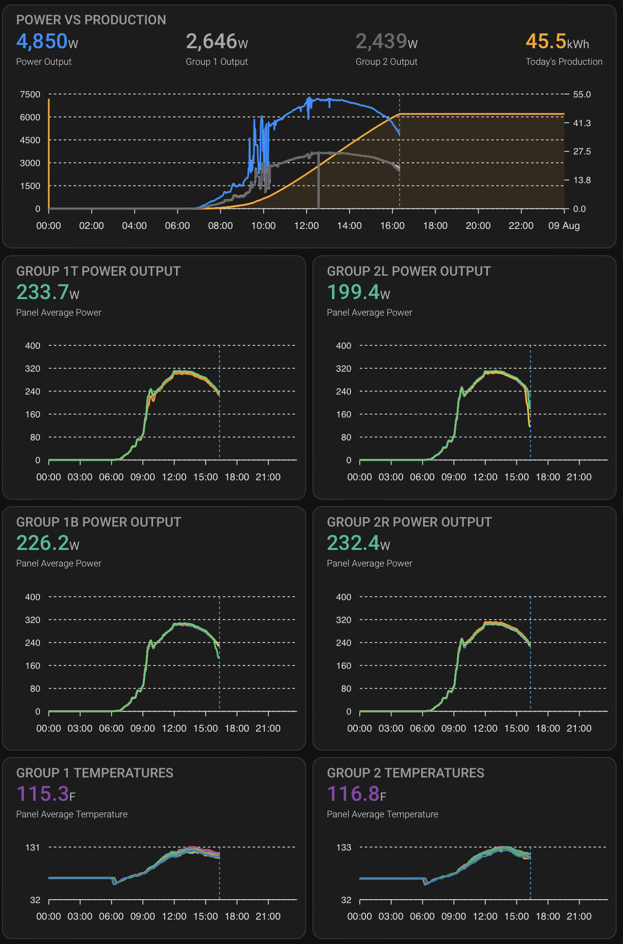
I have 24 panels in two groups of 12 panels each, each group has 2 rows or columns. It is hard to see, but each panel is graphed, and when you hover over it, you can see individual readings.
Other integrations
I have not personally investigated other integrations. If you need something that works out of the box, you’ll have to Google around and give things a try. If you can do a little programming, look at the resources mentioned at the start of this writeup. Several of them have GitHub repositories with code in them. At the very least it will show you how it is done, or you can modify the code to suit your needs.
API information
The Sunpower Console API recognizes a bunch of specific commands. The commands are issued by executing a GET request over HTTP to the URL that looks like this:
http://<rpi address>/cgi-bin/dl_cgi?Command=<command name>
Below, I document each command I know about. Some commands require their name as the Command query parameter, and some require adding your system’s serial number using SerialNumber. See documentation. In the DeviceList command, I will show full response headers and body, but in subsequent documentation, I will only show the body and explanations of what you see there.
The headers indicate that not only GET commands but also POST, DELETE, and PUT are allowed. This would suggest this is a full so-called REST API. I have not attempted to do any of those interactions. If they even work, there is potential for messing something up. Since my system is not for experimentation but rather for power production, I do not want to take that risk. Be warned!
You will note that several commands return data with some keys listed in all uppercase and others in all lowercase. It appears the UPPERCASE ones are device properties/attributes and the lowercase ones are performance indicators.
GET /cgi-bin/dl_cgi?Command=DeviceList
This command gets a complete list of all known PVS devices and their status and performance descriptors. There seem to be three device types:
- Supervisor. This seems to be the main entity that controls everything
- Power meter, which comes in a production and consumption version. The latter will show up even if no consumption metering kit is installed, but kWh information should stay at 0.
- Inverter. There may be as many of these as you have micro-inverters (panels).
The output body below has fake serial numbers and omits all but the first inverter. This way, you can see an example of each device type in the output. Details are discussed below the body.
You will also note the result part of the response. I have never seen anything but success but it stands to reason that if it says anything but success, the rest of the response should not be interpreted.
NOTE: This command may take quite a while. On my PVS6 system with 24 panels it takes between 6 and 7 seconds to return all results!
-
Response 200 (application/json)
-
Headers
1
2
3
4
5
6
7
8
9
HTTP/1.1 200 OK
Content-Type: application/json
Access-Control-Allow-Methods: GET,POST,DELETE,PUT
Pragma: no-cache
dlcgi-build-time: Sep 15 2021 00:05:00
Access-Control-Allow-Origin: *
Access-Control-Allow-Headers: Content-Type
Cache-Control: no-cache, no-store, no-cache, must-revalidate, post-check=0, pre-check=0
Server: lighttpd/1.4.51
-
Body
1
2
3
4
5
6
7
8
9
10
11
12
13
14
15
16
17
18
19
20
21
22
23
24
25
26
27
28
29
30
31
32
33
34
35
36
37
38
39
40
41
42
43
44
45
46
47
48
49
50
51
52
53
54
55
56
57
58
59
60
61
62
63
64
65
66
67
68
69
70
71
72
73
74
75
76
77
78
79
80
81
82
83
84
85
86
87
88
89
90
91
92
93
94
95
96
97
{
	"devices":	[{
			"DETAIL":	"detail",
			"STATE":	"working",
			"STATEDESCR":	"Working",
			"SERIAL":	"ZT01234567890ABCDEF",
			"MODEL":	"PV Supervisor PVS6",
			"HWVER":	"6.02",
			"SWVER":	"2021.9, Build 41001",
			"DEVICE_TYPE":	"PVS",
			"DATATIME":	"2021,10,27,07,25,00",
			"dl_err_count":	"0",
			"dl_comm_err":	"480",
			"dl_skipped_scans":	"0",
			"dl_scan_time":	"1",
			"dl_untransmitted":	"5539",
			"dl_uptime":	"85428",
			"dl_cpu_load":	"0.28",
			"dl_mem_used":	"73704",
			"dl_flash_avail":	"67599",
			"panid":	1234567890,
			"CURTIME":	"2021,10,27,07,28,13"
		}, {
			"ISDETAIL":	true,
			"SERIAL":	"PVS6M12345678p",
			"TYPE":	"PVS5-METER-P",
			"STATE":	"working",
			"STATEDESCR":	"Working",
			"MODEL":	"PVS6M0400p",
			"DESCR":	"Power Meter PVS6M12345678p",
			"DEVICE_TYPE":	"Power Meter",
			"SWVER":	"3000",
			"PORT":	"",
			"DATATIME":	"2021,10,27,07,28,12",
			"ct_scl_fctr":	"50",
			"net_ltea_3phsum_kwh":	"11.34",
			"p_3phsum_kw":	"0",
			"q_3phsum_kvar":	"0",
			"s_3phsum_kva":	"0",
			"tot_pf_rto":	"1",
			"freq_hz":	"60",
			"CAL0":	"50",
			"origin":	"data_logger",
			"OPERATION":	"noop",
			"CURTIME":	"2021,10,27,07,28,13"
		}, {
			"ISDETAIL":	true,
			"SERIAL":	"PVS6M12345678c",
			"TYPE":	"PVS5-METER-C",
			"STATE":	"working",
			"STATEDESCR":	"Working",
			"MODEL":	"PVS6M0400c",
			"DESCR":	"Power Meter PVS6M12345678c",
			"DEVICE_TYPE":	"Power Meter",
			"SWVER":	"3000",
			"PORT":	"",
			"DATATIME":	"2021,10,27,07,28,13",
			"ct_scl_fctr":	"100",
			"net_ltea_3phsum_kwh":	"0",
			"p_3phsum_kw":	"0",
			"q_3phsum_kvar":	"0",
			"s_3phsum_kva":	"0",
			"tot_pf_rto":	"0",
			"freq_hz":	"60",
			"i1_a":	"0",
			"i2_a":	"0",
			"v1n_v":	"116.5863",
			"v2n_v":	"116.4296",
			"v12_v":	"233.0139",
			"p1_kw":	"0",
			"p2_kw":	"0",
			"neg_ltea_3phsum_kwh":	"0",
			"pos_ltea_3phsum_kwh":	"0",
			"CAL0":	"100",
			"origin":	"data_logger",
			"OPERATION":	"noop",
			"CURTIME":	"2021,10,27,07,28,14"
		}, {
			"ISDETAIL":	true,
			"SERIAL":	"E00123456000001",
			"TYPE":	"SOLARBRIDGE",
			"STATE":	"error",
			"STATEDESCR":	"Error",
			"MODEL":	"AC_Module_Type_E",
			"DESCR":	"Inverter E00122125092032",
			"DEVICE_TYPE":	"Inverter",
			"PANEL":	"SPR-X22-360-E-AC",
			"SWVER":	"4.21.3",
			"PORT":	"",
			"MOD_SN":	"R36M20579663",
			"NMPLT_SKU":	"",
			"origin":	"data_logger",
			"OPERATION":	"noop",
			"CURTIME":	"2021,10,28,09,03,43"
		}],
	"result":	"succeed"
}
-
Detail for supervisor
Most of the properties are self-explanatory. The DATATIME indicates the timestamp when the presented information last changed, whereas CURTIME should be the timestamp of the request (or something close to it). The timestamps are in UTC! Observation of DATATIME on my system shows that the minutes component is always a multiple of 5 minutes and seconds is always 0. So, if you are interested in getting timely information, perform the call after the start of each 5-minute interval. You can interrogate more often, but if timing is not important, don’t stress the PVS6 by constantly asking for DeviceList.
The meaning of the performance indicators can only be guessed by observation and a little knowledge (dl probably means “data logger”):
dl_err_count: Number of errors since last report?dl_comm_err: Number of communication errors? (Not sure what kind)dl_skipped_scans: Best guess this counts when the supervisor scans the PLC network for inverters and it decides it needs to skip a scandl_scan_time: Probably related somehow to the above mentioned scandl_untransmitted: Number of not yet transmitted (to SunPower) events/records?dl_uptime: The number of seconds the data logger has been running. I observed it being lower than a previously seen value (the prior value was almost 24h, the new value was a little over 1.5h). I was not aware of a power outage in between, so either there was a restart for power reasons or something else, or perhaps the device restarts itself periodically (somewhat lousy safeguard against memory leaks), or something else. Also, see the remark below.dl_cpu_load: CPU load average as it existed (possibly averaged over 5 minutes) atDATATIMEdl_mem_used: amount of memory in use. Assuming the motherboard has little memory this is probably in kiBdl_flash_avail: amount of free space on flash device. Assumed in kIB
During experimentation I occasionally encountered this response:
1
2
3
4
5
6
7
8
HTTP/1.0 503 Service Unavailable
Cache-Control: no-cache
Connection: close
Content-Type: text/html

<html><body><h1>503 Service Unavailable</h1>
No server is available to handle this request.
</body></html>
That would stay that way for a few minutes. After a successful retry, I would see dl_uptime as a very low number, indicating that the supervisor/datalogger had apparently restarted. It is not clear if I caused the crash/restart, or it “just happens”.
Detail for power meter
Reports show that power meter data is updated more frequently than supervisor information. Reports indicate at least every 5 seconds. The power meter’s properties are fairly self-explanatory. One thing to note is that the DESCR property contains the meter’s serial number inside its name. The name ends with the letter “p,” indicating this is the “production” meter, or the letter “c,” indicating the consumer meter. Ditto for the MODEL property. Also present, as described for the supervisor are DATATIME and CURTIME.
The CAL0 property indicates the sensor’s current capacity for the calibration-reference CT sensor. It will be “50” (50A) for the production meter, and either “100” or “200” for consumption. Note that the ct_scl_fctr contains the capacity for the actual sensor.
The meaning of the performance indicators can only be guessed by observation and a little knowledge:
ct_scl_fctr: Current capacity for the actual CT sensor usednet_ltea_3phsum_kwh: Net cumulative energy, in kWh, across all three phasesp_3phsum_kw: Average real powerq_3phsum_kvar: Cumulative “reactive” power, in kVA or kW, across all three phases (since ?)s_3phsum_kva: Cumulative “apparent” power, in kVA or kW, across all three phases (since ?)tot_pf_rto: Power factor ratio, defined asreal powerdivided byapparant powerfreq_hz: Operating frequency (typically around 60 Hz in the US)
The above performance indicators are present in both production and consumer meters. The following are additionally available in the consumption meter:
i1_a: Supply current, in A, on CT1 leadi2_a: Supply current, in A, on CT2 leadv1n_v: Supply voltage CT1 lead (relative to neutral, typically in the 110-120 V range)v2n_v: Supply voltage CT2 lead (relative to neutral, typically in the 110-120 V range)v12_v: Supply Voltage sum across CT1 and CT2 leads (typically in the 220-140 V range)p1_kw: Lead 1 average power in kW. Can be positive (excess back to utility) or negative (used from utility)p2_kw: Lead 2 average power in kW. Can be positive (excess back to utility) or negative (used from utility)neg_ltea_3phsum_kwh: Cumulative energy, in kWh, across all three phases, consumed from utilitypos_ltea_3phsum_kwh:Cumulative energy, in kWh, across all three phases, supplied to utility
Note that “net” utility consumption can be computed by subtracting the ltea_3phsum_kwh numbers.
The “production” meter only measures power produced by the PV array. At night, when there is no production, this number can go slightly negative. This is the energy consumed by the PV electronics (inverters). It has been reported in the -15 W range, but that may be specific for a certain number of panels and model micro inverters. Since this power is always needed, that would mean that on a daily basis, 24 x 15 Wh = 0.36 kWh from production is never available to supply the home or back to the utility. If you insist you can try to factor this into any calculations, but I will suggest it is too low to worry about. In a 6 kW system, this would represent 15 / 6000 = 0.25%.
Detail for micro inverter
The information for the inverter(s) has the usual UPPERCASE properties. It should be noted that when the panels are not powered, the returned STATE will be error. This presumes that, at some point, the power was on (typically during initial installation and commissioning), and the actual devices were discovered.
The following performance data seems to be available (but is not included where STATE is not “working”):
module_serial: Equal toMOD_SNand contains the inverter module serial number (first seen in version 2021.11)hw_version: Hardware version number (first seen in version 2021.11)freq_hz: Operating Frequency in Hz (typically around 60 Hz in the US)stat_ind: Status indicator (first seen in version 2021.11)i_3phsum_a: AC Current (in A)p_3phsum_kw: AC Power (in kW)vln_3phavg_v: AC Voltage (in V)ltea_3phsum_kwh: Total energy (in kWh)i_mppt1_a: DC Current (in A) for MPPT (Maximum Power Point Tracking)v_mppt1_v: DC Voltage (in V) for MPPT (Maximum Power Point Tracking)p_mppt1_kw: DC Power (in kW) for MPTT (Maximum Power Point Tracking) (first seen in version 2021.11)p_mpptsum_kw: DC Power (in kW) for MPPT (Maximum Power Point Tracking) (seems replaced byp_mppt1_kwsince version 2021.11)t_htsnk_degc: Heatsink temperature (degrees Celsius)
Additional devices for battery equipped systems
You will find additional devices in the response if you also have an attached ESS battery system (not shown above). These devices have been “seen” in such an installation and details follow below:
- HUB+
- EQUINOX-MI0 (That is an O for Input/Output)
- PV-DISCONNECT
- GATEWAY: Controller device for everything the PVS6 does not manage (batteries/inverter etc)
- SCHNEIDER-XWPRO: Inverter/charger
- EQUINOX-BMS: BMS = Battery Management System
- BATTERY: An actual battery, there may be multiple of these
- EQUINOX-ESS: ESS = Energy Storage System
Detail for HUB+
The HUB+ is described as a model “SunPower MIDC” with the device type “HUB+.” The cabinet houses a sub-panel for the battery-backed-up loads in your house, controls the solar + storage system for optimal performance, and manages transitions from utility power to battery power.
It also houses the MIDC (Microgrid Interconnect Device Controller). It connects to the PVS6 via port J8 for the 12 VDC power supply and port J13 for the CAN bus (not to be confused with the ModBus). Finally, J10 is the RS-485 connection from the PVS6.
The device manages the microgrid (everything in the system that possibly generates power, including PV panels and batteries) and the MID or Microgrid Interconnect Device. The latter device will decouple the utility side from the PV/Battery side in case of a utility shutdown. The MIDC commands this decoupling. However, there is also a physical switch in the MID, operated by a screwdriver, for manual disconnect: turned to the left, it is in the disconnected state.
The data section generally looks like this:
1
2
3
4
5
6
7
8
9
10
11
12
13
14
15
16
17
18
{
	"ISDETAIL":	true,
	"SERIAL":	"SY01234567890ABCDEF",
	"TYPE":	"HUB+",
	"STATE":	"error",
	"STATEDESCR":	"Error",
	"MODEL":	"SunPower MIDC",
	"DESCR":	"HUB+ SY01234567890ABCDEF",
	"DEVICE_TYPE":	"HUB+",
	"hw_version":	"1.5.0",
	"interface":	"ttymxc5",
	"slave":	220,
	"SWVER":	"0.7.22",
	"PORT":	"P0, Modbus, Slave 220",
	"origin":	"data_logger",
	"OPERATION":	"noop",
	"CURTIME":	"2022,05,26,14,50,32"
}
Note that this “device” and others described here list “STATE” as “error”. This is most likely due to the limited test setup. We will work to capture output in the regular state.
Clearly, there is no performance-related data here, so the attribute of most interest would be the “STATE”.
Detail for EQUINOX-MIO
The MIO is described as a model “SunPower MIO” with device type “ESS Hub. “MIO” stands for “Multi I/O.” It is connected to the HUB+ (J1 connector) and possibly to the MIO in other battery cabinets (J2 connector). Not all functions are clear, but there are connections between this component and two fans inside the cabinet. It also has CAN bus connections to the gateway, battery, and LED board (in the door).
The data section generally looks like this:
1
2
3
4
5
6
7
8
9
10
11
12
13
14
15
16
17
18
19
20
21
22
23
24
25
26
27
28
29
{
	"ISDETAIL":	true,
	"SERIAL":	"SY01234567890ABCDEF",
	"TYPE":	"EQUINOX-MIO",
	"STATE":	"working",
	"STATEDESCR":	"Working",
	"MODEL":	"SunPower MIO",
	"DESCR":	"ESS Hub SY01234567890ABCDEF",
	"DEVICE_TYPE":	"ESS Hub",
	"hw_version":	"0.4.0",
	"interface":	"ttymxc5",
	"parent":	11,
	"slave":	221,
	"SWVER":	"0.7.10",
	"PORT":	"P0, Modbus, Slave 221",
	"DATATIME":	"2022,05,26,14,50,20",
	"t_degc":	"36",
	"humidity":	"20",
	"v_dcdc_spply_v":	"11.43",
	"v_spply_v":	"11.364",
	"v_gateway_v":	"11.419",
	"fan_actv_fl":	"0",
	"fw_error":	"0",
	"event_history":	"2112",
	"origin":	"data_logger",
	"OPERATION":	"noop",
	"PARENT":	"00001ABC1234_01234567890ABCDEF",
	"CURTIME":	"2022,05,26,14,50,32"
}
The performance data seems to include:
t_degc: External/ambient (to the cabinets, not necessarily outside) temperature in degrees Celcius.humidity: External/ambient humidity in percent (0-100)v_dcdc_spply_v: The DC to DC supply voltage (i.e. what the batteries provide) before the inverterv_spply_v: Another form of supply voltage, unclear to whatv_gateway_v: Voltage to/for the gatewayfan_actv_fl: Fan active flag, 0 for inactive, 1 for active (needs to be verified)fw_error: Error count for firmwareevent_history: Count of “events” seen so far
Detail for PV-DISCONNECT
The PV-DISCONNECT is described as a model “SunPower PV Disconnect Relay” with the device type “PV Disconnect.” It represents the circuitry or functionality that disconnects the PV system from the grid tie when reverting to battery operation and vice versa when resuming grid connection. As such, it would be commanded to do so by one of the other system components.
The data section generally looks like this:
1
2
3
4
5
6
7
8
9
10
11
12
13
14
15
16
17
18
19
20
21
22
23
24
25
26
27
28
29
30
{
	"ISDETAIL":	true,
	"SERIAL":	"SY01234567890ABCDEF",
	"TYPE":	"PV-DISCONNECT",
	"STATE":	"working",
	"STATEDESCR":	"Working",
	"MODEL":	"SunPower PV Disconnect Relay",
	"DESCR":	"PV Disconnect SY01234567890ABCDEF",
	"DEVICE_TYPE":	"PV Disconnect",
	"hw_version":	"0.2.0",
	"interface":	"ttymxc5",
	"slave":	230,
	"SWVER":	"0.2.13",
	"PORT":	"P0, Modbus, Slave 230",
	"DATATIME":	"2022,05,26,14,50,30",
	"event_history":	"32",
	"fw_error":	"0",
	"relay_mode":	"0",
	"relay1_state":	"1",
	"relay2_state":	"1",
	"relay1_error":	"0",
	"relay2_error":	"0",
	"v1n_grid_v":	"123.1",
	"v2n_grid_v":	"122.5",
	"v1n_pv_v":	"122.8",
	"v2n_pv_v":	"122.5",
	"origin":	"data_logger",
	"OPERATION":	"noop",
	"CURTIME":	"2022,05,26,14,50,32"
}
The performance data seems to include:
relay_mode: Flag with 0 suspected meaning utility operations, 1 battery operationsrelay1_state: State of relay 1 (0 or 1)relay1_error: Error count for relay 1relay2_state: State of relay 2 (0 or 1)relay2_error: Error count for relay 2v1n_grid_v: Voltage differential between phase 1 neutral and gridv2n_grid_v: Voltage differential between phase 2 neutral and gridv1n_pv_v: Voltage differential between phase 1 neutral and PV systemv2n_pv_v: Voltage differential between phase 2 neutral and PV systemfw_error: Error count for firmwareevent_history: Count of “events” seen so far
Detail for GATEWAY
The GATEWAY is described as a model “SchneiderElectric-ConextGateway” with the device type “Gateway.” This product ties together the whole battery system, including the inverter (not to be confused with the PV micro inverters). It provides an interface for configuration and performance observations. It also provides a “ Modbus “ mechanism (Module Bus or Modular Bus). This interface allows accessing certain components attached to it (you can see this in the “PORT” specifications for the various device details). This is an RS-485-based serial bus.
The data section generally looks like this:
1
2
3
4
5
6
7
8
9
10
11
12
13
14
15
16
17
18
{
	"ISDETAIL":	true,
	"SERIAL":	"BC1234006789",
	"TYPE":	"GATEWAY",
	"STATE":	"error",
	"STATEDESCR":	"Error",
	"MODEL":	"SchneiderElectric-ConextGateway",
	"DESCR":	"Gateway BC1234006789",
	"DEVICE_TYPE":	"Gateway",
	"interface":	"sunspec",
	"mac_address":	"d8:a9:ab:cd:12:34",
	"slave":	1,
	"SWVER":	"V1",
	"PORT":	"P0, SunSpec, Slave 1",
	"origin":	"data_logger",
	"OPERATION":	"noop",
	"CURTIME":	"2022,05,26,14,50,33"
}
There appears to be no meaningful performance data, outside the communication port specification.
Detail for SCHNEIDER-XWPRO
The SCHNEIDER-XWPRO is described as a model “SchneiderElectric-XW6848-21” with the device type “Storage Inverter.” This is the DC to AC inverter (and vice versa) used to feed the backed-up circuits (panel inside the HUB+) during battery-only operations. It converts (what appears to be a 12V battery) to 120V AC. It also functions as the charger circuitry for the batteries.
It is a 120/240V/60Hz pure sine wave inverter that can operate in single-phase, split-phase, or three-phase modes and produce up to 6,800 W of continuous power.
The data section generally looks like this:
1
2
3
4
5
6
7
8
9
10
11
12
13
14
15
16
17
18
19
20
{
    "ISDETAIL":	true,
	"SERIAL":	"00001ABC1234",
	"TYPE":	"SCHNEIDER-XWPRO",
	"STATE":	"error",
	"STATEDESCR":	"Error",
	"MODEL":	"SchneiderElectric-XW6848-21",
	"DESCR":	"Storage Inverter 00001ABC1234",
	"DEVICE_TYPE":	"Storage Inverter",
	"interface":	"sunspec",
	"mac_address":	"d8:a9:ab:cd:12:34",
	"parent":	11,
	"slave":	10,
	"SWVER":	"V1",
	"PORT":	"P0, SunSpec, Slave 10",
	"origin":	"data_logger",
	"OPERATION":	"noop",
	"PARENT":	"00001ABC1234_01234567890ABCDEF",
	"CURTIME":	"2022,05,26,14,50,33"
}
There appears to be no meaningful performance data outside the communication port specification.
Detail for EQUINOX-BMS
The EQUINOX-BMS is described as a model “EQUINOX-BMS” with device type “ESS BMS.” This is the battery management sub-system.
The data section generally looks like this:
1
2
3
4
5
6
7
8
9
10
11
12
13
14
15
16
17
18
19
{
    "ISDETAIL":	true,
	"SERIAL":	"BC123400678933751040",
	"TYPE":	"EQUINOX-BMS",
	"STATE":	"error",
	"STATEDESCR":	"Error",
	"MODEL":	"SchneiderElectric-SP1",
	"DESCR":	"ESS BMS BC01234567890ABCDEF",
	"DEVICE_TYPE":	"ESS BMS",
	"interface":	"sunspec",
	"mac_address":	"d8:a9:ab:cd:12:34",
	"parent":	11,
	"slave":	230,
	"PORT":	"P0, SunSpec, Slave 230",
	"origin":	"data_logger",
	"OPERATION":	"noop",
	"PARENT":	"00001ABC1234_01234567890ABCDEF",
	"CURTIME":	"2022,05,26,14,50,33"
}
There is no meaningful performance data outside the communication port specification.
Detail for BATTERY
The BATTERY is described as a model “POWERAMP-Komodo 1.2” (in this particular installation at least) with the device type “Battery.” This represents an actual battery in the system, and as such, there may be multiple such entries (in a single cabinet installation, there are two entries, one for each battery inside the cabinet).
The data section generally looks like this:
1
2
3
4
5
6
7
8
9
10
11
12
13
14
15
16
17
18
19
{
	"ISDETAIL":	true,
	"SERIAL":	"M00122109A0355",
	"TYPE":	"BATTERY",
	"STATE":	"error",
	"STATEDESCR":	"Error",
	"MODEL":	"POWERAMP-Komodo 1.2",
	"DESCR":	"Battery M00122109A0355",
	"DEVICE_TYPE":	"Battery",
	"hw_version":	"4.34",
	"interface":	"none",
	"parent":	11,
	"SWVER":	"2.8",
	"PORT":	"P0, None, Slave -1",
	"origin":	"data_logger",
	"OPERATION":	"noop",
	"PARENT":	"00001ABC1234_01234567890ABCDEF",
	"CURTIME":	"2022,05,26,14,50,34"
}
Note that there is no performance-type data, and the battery entries only seem to differ in their serial numbers. The port specification indicates that they are not directly (individually) addressable. However, information about them might be available through the Modbus system (via the Gateway or the BMS).
Detail for EQUINOX-ESS
The EQUINOX-ESS is described as a model “SPWR-Equinox-model” with the device type “Energy Storage System.” It is not clear to me yet what this represents. It seems all other components comprise the whole system, so perhaps this is just an entry representing the “whole.”
The data section generally looks like this:
1
2
3
4
5
6
7
8
9
10
11
12
13
14
15
16
17
{
	"ISDETAIL":	true,
	"SERIAL":	"00001ABC1234_01234567890ABCDEF",
	"TYPE":	"EQUINOX-ESS",
	"STATE":	"error",
	"STATEDESCR":	"Error",
	"MODEL":	"SPWR-Equinox-model",
	"DESCR":	"Energy Storage System 00001ABC1234_01234567890ABCDEF",
	"DEVICE_TYPE":	"Energy Storage System",
	"hw_version":	"0",
	"interface":	"none",
	"SWVER":	"0",
	"PORT":	"P0, Parent, Slave -1",
	"origin":	"data_logger",
	"OPERATION":	"noop",
	"CURTIME":	"2022,05,26,14,50,35"
}
Note that there is no performance type data.
GET /cgi-bin/dl_cgi?Command=Get_Comm&SerialNumber=ZT01234567890ABCDEF
This command requires the addition of the serial number. If there are multiple supervisors on the internal SunPower network, it can select the correct one. The command returns information about the available network interfaces.
-
Body
1
2
3
4
5
6
7
8
9
10
11
12
13
14
15
16
17
18
19
20
21
22
23
24
25
26
27
28
29
30
31
32
33
34
35
36
37
38
39
40
41
42
43
44
45
46
47
48
49
50
51
{
	"result":	"succeed",
	"networkstatus":	{
		"interfaces":	[{
				"interface":	"wan",
				"internet":	"down",
				"ipaddr":	"",
				"link":	"disconnected",
				"mode":	"wan",
				"sms":	"unreachable",
				"state":	"down"
			}, {
				"interface":	"plc",
				"internet":	"down",
				"ipaddr":	"",
				"link":	"disconnected",
				"pairing":	"unpaired",
				"sms":	"unreachable",
				"speed":	0,
				"state":	"down"
			}, {
				"interface":	"sta0",
				"internet":	"up",
				"ipaddr":	"192.168.10.239",
				"signal":	"-48",
				"sms":	"reachable",
				"ssid":	"Starfield",
				"status":	"connected"
			}, {
				"interface":	"cell",
				"internet":	"down",
				"ipaddr":	"",
				"is_alwayson":	false,
				"is_primary":	false,
				"link":	"connected",
				"modem":	"MODEM_OK",
				"provider":	"UNKNOWN",
				"signal":	0,
				"sim":	"SIM_READY",
				"sms":	"unreachable",
				"state":	"DOWN",
				"status":	"NOT_REGISTERED"
			}],
		"system":	{
			"interface":	"sta0",
			"internet":	"up",
			"sms":	"reachable"
		},
		"ts":	"1635315583"
	}
}
GET /cgi-bin/dl_cgi?Command=Start
This command starts a configuration session. I am not sure what that means, but I am guessing it is related to the ability to use this as a REST API where any changes made using PUT, POST, and DELETE cannot be done until a session is started version and are not made permanent until (a) the result is a valid configuration, and (b) the session is “stopped” (see below).
-
Body
1
2
3
4
5
6
7
8
9
10
11
12
13
14
15
16
{
	"result":	"succeed",
	"supervisor":	{
		"SWVER":	"2021.9, Build 41001",
		"SERIAL":	"ZT01234567890ABCDEF",
		"MODEL":	"PVS6",
		"BUILD":	41001,
		"FWVER":	"1.0.0",
		"SCVER":	16504,
		"EASICVER":	131329,
		"SCBUILD":	1185,
		"WNSERIAL":	16,
		"WNMODEL":	400,
		"WNVER":	3000
	}
}
GET /cgi-bin/dl_cgi?Command=Stop
This command stops the configuration session. Not (yet) clear what that is.
- Body
1
2
3
{
	"result":	"succeed"
}
GET /cgi-bin/dl_cgi?Command=CheckFW
This command checks if a firmware update is available. If not, it returns “none,” otherwise, it returns the URL for the firmware file.
-
Body
1
2
3
{
	"url":	"none"
}
GET /cgi-bin/dl_cgi?Command=DeviceDetails&SerialNumber=ZT01234567890ABCDEF
I found this command mentioned somewhere, but I have not gotten it to work
-
Body
1
{	"result":	"unknown command"}
GET /cgi-bin/dl_cgi?Command=GridProfileGet
This command exposes the currently selected/active grid profile (for a full list see the GridProfileRefresh command).
-
Body
1
2
3
4
5
6
7
8
9
10
{
	"result":	"succeed",
	"active_name":	"IEEE-1547a-2014 + 2020 CA Rule21",
	"active_id":	"816bf3302d337a42680b996227ddbc46abf9cd05",
	"pending_name":	"IEEE-1547a-2014 + 2020 CA Rule21",
	"pending_id":	"816bf3302d337a42680b996227ddbc46abf9cd05",
	"percent":	100,
	"supported_by":	"ALL",
	"status":	"success"
}
GET /cgi-bin/dl_cgi?Command=GridProfileRefresh
This command seems to “refresh” in the internal database of supply grid profiles. The profiles have a unique ID, a descriptive name, refer to a file with metadata about the profile (filename), and have a list of zip codes (zipcodes) to which it (may) apply.
-
Body
1
2
3
4
5
6
7
8
9
10
11
12
13
14
15
16
17
18
19
20
21
22
23
24
25
26
27
28
29
30
31
32
33
34
35
36
37
38
39
40
41
42
43
44
45
46
47
48
49
50
51
52
53
54
55
56
57
58
59
60
61
62
63
64
65
66
67
68
69
70
71
72
73
74
75
76
77
78
79
80
81
82
83
84
85
86
87
88
89
90
91
92
93
94
95
96
97
98
99
100
101
102
103
104
105
106
107
108
109
110
111
112
113
114
115
116
117
118
119
120
121
122
123
124
125
126
127
128
129
130
131
132
133
134
135
136
137
138
139
140
141
142
143
144
145
146
147
148
149
150
151
152
153
154
155
156
157
158
159
160
161
162
163
164
165
166
167
168
169
170
171
172
173
174
175
176
177
178
179
180
181
182
183
184
185
186
187
188
189
190
191
192
193
194
195
196
197
198
199
200
201
202
203
204
205
206
207
208
209
210
211
212
213
214
215
216
217
218
219
220
221
222
223
224
225
226
227
228
229
230
231
232
233
234
235
236
237
238
239
240
241
242
243
244
245
246
247
248
249
250
251
252
253
254
255
256
257
258
259
260
261
262
263
264
265
266
267
268
269
270
271
272
273
274
275
276
277
278
279
280
281
282
283
284
285
286
287
288
289
290
291
292
293
294
295
296
297
298
299
300
301
302
303
304
305
306
307
308
309
310
311
312
313
314
315
316
317
318
319
320
321
322
323
324
325
326
327
328
329
330
331
332
333
334
335
336
337
338
339
340
341
342
343
344
345
346
347
348
349
350
351
352
353
354
355
356
357
358
359
360
361
362
363
364
365
366
367
368
369
370
371
372
373
374
375
376
377
378
379
380
381
382
383
384
385
386
387
388
389
390
391
392
393
394
395
396
397
398
399
400
401
402
403
404
405
406
407
408
409
410
411
412
413
414
415
416
417
418
419
420
421
422
423
424
425
426
427
428
429
430
431
432
433
434
435
436
437
438
439
440
441
442
443
444
445
446
447
448
449
450
451
452
453
454
455
456
457
458
459
460
461
462
463
464
465
466
467
468
469
470
471
472
473
474
475
476
477
478
479
480
481
482
483
484
485
486
487
488
489
490
491
492
493
494
495
496
497
498
499
500
501
502
503
504
505
506
507
508
509
510
511
512
513
514
515
516
517
518
519
520
521
522
523
524
525
526
527
528
529
530
531
532
533
534
535
536
537
538
539
540
541
542
543
544
545
546
547
548
549
550
551
552
553
554
555
556
557
558
559
560
561
562
563
564
565
566
567
568
569
570
571
572
573
574
575
576
577
578
579
580
581
582
583
584
585
586
587
588
589
590
591
592
593
594
595
596
597
598
599
600
601
602
603
604
605
606
607
608
609
610
611
612
613
614
615
616
617
618
619
620
621
{
	"result":	"succeed",
	"success":	true,
	"creation":	1600704253,
	"profiles":	[{
			"selfsupply":	true,
			"zipcodes":	[{
					"max":	96898,
					"min":	96701
				}],
			"default":	false,
			"filename":	"8c9c4170.meta",
			"id":	"8c9c4170457c88f6dcee7216357681d580a3b9bd",
			"name":	"HECO OMH R14H (Legacy)"
		}, {
			"selfsupply":	true,
			"zipcodes":	[{
					"max":	96898,
					"min":	96701
				}],
			"default":	false,
			"filename":	"f169fe0d.meta",
			"id":	"f169fe0dc993987c5f105df9d651a284e8031c5a",
			"name":	"HI GSUI OMH R14H 2018"
		}, {
			"selfsupply":	true,
			"zipcodes":	[{
					"max":	96898,
					"min":	96701
				}],
			"default":	false,
			"filename":	"2d8a06aa.meta",
			"id":	"2d8a06aa4812913510c7955cabaf114e5432fe67",
			"name":	"HI GSUI OMH R14H 2018 + V/W"
		}, {
			"selfsupply":	false,
			"zipcodes":	[{
					"max":	96162,
					"min":	90001
				}],
			"default":	false,
			"filename":	"816bf330.meta",
			"id":	"816bf3302d337a42680b996227ddbc46abf9cd05",
			"name":	"IEEE-1547a-2014 + 2020 CA Rule21"
		}, {
			"selfsupply":	false,
			"zipcodes":	[{
					"max":	-1,
					"min":	-1
				}],
			"default":	false,
			"filename":	"db54e057.meta",
			"id":	"db54e057f901db5d7907af561688f0af555c563d",
			"name":	"CA CPUC R21 Reactive Power Priority"
		}, {
			"selfsupply":	false,
			"zipcodes":	[{
					"max":	-1,
					"min":	-1
				}],
			"default":	false,
			"filename":	"43daefaa.meta",
			"id":	"43daefaa4404f4674edd2ad89c175a65f3cebc51",
			"name":	"California CPUC Rule21"
		}, {
			"selfsupply":	false,
			"zipcodes":	[81121, 81122, 81128, 81130, 81137, 81147, 81157, 81235, 81301, 81302, 81303, 81326, 81328, 81329],
			"default":	false,
			"filename":	"954a2a24.meta",
			"id":	"954a2a240698d9c006afb72fc93febc622b296eb",
			"name":	"La Plata Electric Assn"
		}, {
			"selfsupply":	false,
			"zipcodes":	[17302, 17309, 17314, 17527, 18014, 18054, 18073, 18074, 18076, 18084, 18901, 18902, 18910, 18912, 18913, 18914, 18915, 18916, 18917, 18922, 18923, 18925, 18926, 18928, 18929, 18931, 18932, 18933, 18934, 18936, 18938, 18940, 18942, 18943, 18944, 18946, 18947, 18949, 18950, 18951, 18954, 18956, 18957, 18958, 18963, 18964, 18966, 18969, 18971, 18974, 18976, 18977, 18979, 18980, 18991, 19001, 19002, 19003, 19004, 19006, 19007, 19008, 19009, 19010, 19012, 19013, 19014, 19015, 19016, 19017, 19018, 19019, 19020, 19021, 19022, 19023, 19025, 19026, 19027, 19028, 19029, 19030, 19031, 19032, 19033, 19034, 19035, 19036, 19037, 19038, 19039, 19040, 19041, 19043, 19044, 19046, 19047, 19048, 19049, 19050, 19052, 19053, 19054, 19055, 19056, 19057, 19058, 19060, 19061, 19063, 19064, 19065, 19066, 19067, 19070, 19072, 19073, 19074, 19075, 19076, 19078, 19079, 19080, 19081, 19082, 19083, 19085, 19086, 19087, 19088, 19089, 19090, 19091, 19092, 19093, 19094, 19095, 19096, 19098, 19099, 19101, 19102, 19103, 19104, 19105, 19106, 19107, 19108, 19109, 19110, 19111, 19112, 19113, 19114, 19115, 19116, 19118, 19119, 19120, 19121, 19122, 19123, 19124, 19125, 19126, 19127, 19128, 19129, 19130, 19131, 19132, 19133, 19134, 19135, 19136, 19137, 19138, 19139, 19140, 19141, 19142, 19143, 19144, 19145, 19146, 19147, 19148, 19149, 19150, 19151, 19152, 19153, 19154, 19155, 19160, 19161, 19162, 19170, 19171, 19172, 19173, 19175, 19176, 19177, 19178, 19179, 19181, 19182, 19183, 19184, 19185, 19187, 19188, 19190, 19191, 19192, 19193, 19194, 19195, 19196, 19197, 19244, 19255, 19301, 19310, 19311, 19312, 19316, 19317, 19318, 19319, 19320, 19330, 19331, 19333, 19335, 19339, 19340, 19341, 19342, 19343, 19344, 19345, 19346, 19347, 19348, 19350, 19351, 19352, 19353, 19354, 19355, 19357, 19358, 19360, 19362, 19363, 19365, 19366, 19367, 19369, 19372, 19373, 19374, 19375, 19376, 19380, 19381, 19382, 19383, 19388, 19390, 19395, 19397, 19398, 19399, 19401, 19403, 19404, 19405, 19406, 19407, 19408, 19409, 19415, 19420, 19421, 19422, 19423, 19424, 19425, 19426, 19428, 19429, 19430, 19432, 19436, 19437, 19438, 19440, 19441, 19442, 19443, 19444, 19446, 19450, 19451, 19453, 19454, 19455, 19456, 19457, 19460, 19462, 19464, 19465, 19468, 19473, 19474, 19475, 19477, 19478, 19480, 19481, 19482, 19484, 19485, 19486, 19490, 19492, 19493, 19494, 19495, 19496, 19520, 19525],
			"default":	false,
			"filename":	"8b82ccd2.meta",
			"id":	"8b82ccd2cfe07c8cc49134fcdcd5edec8845cd5d",
			"name":	"PECO Voltage Trip High (254V)"
		}, {
			"selfsupply":	false,
			"zipcodes":	[17302, 17309, 17314, 17527, 18014, 18054, 18073, 18074, 18076, 18084, 18901, 18902, 18910, 18912, 18913, 18914, 18915, 18916, 18917, 18922, 18923, 18925, 18926, 18928, 18929, 18931, 18932, 18933, 18934, 18936, 18938, 18940, 18942, 18943, 18944, 18946, 18947, 18949, 18950, 18951, 18954, 18956, 18957, 18958, 18963, 18964, 18966, 18969, 18971, 18974, 18976, 18977, 18979, 18980, 18991, 19001, 19002, 19003, 19004, 19006, 19007, 19008, 19009, 19010, 19012, 19013, 19014, 19015, 19016, 19017, 19018, 19019, 19020, 19021, 19022, 19023, 19025, 19026, 19027, 19028, 19029, 19030, 19031, 19032, 19033, 19034, 19035, 19036, 19037, 19038, 19039, 19040, 19041, 19043, 19044, 19046, 19047, 19048, 19049, 19050, 19052, 19053, 19054, 19055, 19056, 19057, 19058, 19060, 19061, 19063, 19064, 19065, 19066, 19067, 19070, 19072, 19073, 19074, 19075, 19076, 19078, 19079, 19080, 19081, 19082, 19083, 19085, 19086, 19087, 19088, 19089, 19090, 19091, 19092, 19093, 19094, 19095, 19096, 19098, 19099, 19101, 19102, 19103, 19104, 19105, 19106, 19107, 19108, 19109, 19110, 19111, 19112, 19113, 19114, 19115, 19116, 19118, 19119, 19120, 19121, 19122, 19123, 19124, 19125, 19126, 19127, 19128, 19129, 19130, 19131, 19132, 19133, 19134, 19135, 19136, 19137, 19138, 19139, 19140, 19141, 19142, 19143, 19144, 19145, 19146, 19147, 19148, 19149, 19150, 19151, 19152, 19153, 19154, 19155, 19160, 19161, 19162, 19170, 19171, 19172, 19173, 19175, 19176, 19177, 19178, 19179, 19181, 19182, 19183, 19184, 19185, 19187, 19188, 19190, 19191, 19192, 19193, 19194, 19195, 19196, 19197, 19244, 19255, 19301, 19310, 19311, 19312, 19316, 19317, 19318, 19319, 19320, 19330, 19331, 19333, 19335, 19339, 19340, 19341, 19342, 19343, 19344, 19345, 19346, 19347, 19348, 19350, 19351, 19352, 19353, 19354, 19355, 19357, 19358, 19360, 19362, 19363, 19365, 19366, 19367, 19369, 19372, 19373, 19374, 19375, 19376, 19380, 19381, 19382, 19383, 19388, 19390, 19395, 19397, 19398, 19399, 19401, 19403, 19404, 19405, 19406, 19407, 19408, 19409, 19415, 19420, 19421, 19422, 19423, 19424, 19425, 19426, 19428, 19429, 19430, 19432, 19436, 19437, 19438, 19440, 19441, 19442, 19443, 19444, 19446, 19450, 19451, 19453, 19454, 19455, 19456, 19457, 19460, 19462, 19464, 19465, 19468, 19473, 19474, 19475, 19477, 19478, 19480, 19481, 19482, 19484, 19485, 19486, 19490, 19492, 19493, 19494, 19495, 19496, 19520, 19525],
			"default":	false,
			"filename":	"65edfb4c.meta",
			"id":	"65edfb4c22bc591b1556f910b6d5097dffb30308",
			"name":	"PECO Voltage Trip High (255V)"
		}, {
			"selfsupply":	false,
			"zipcodes":	[17302, 17309, 17314, 17527, 18014, 18054, 18073, 18074, 18076, 18084, 18901, 18902, 18910, 18912, 18913, 18914, 18915, 18916, 18917, 18922, 18923, 18925, 18926, 18928, 18929, 18931, 18932, 18933, 18934, 18936, 18938, 18940, 18942, 18943, 18944, 18946, 18947, 18949, 18950, 18951, 18954, 18956, 18957, 18958, 18963, 18964, 18966, 18969, 18971, 18974, 18976, 18977, 18979, 18980, 18991, 19001, 19002, 19003, 19004, 19006, 19007, 19008, 19009, 19010, 19012, 19013, 19014, 19015, 19016, 19017, 19018, 19019, 19020, 19021, 19022, 19023, 19025, 19026, 19027, 19028, 19029, 19030, 19031, 19032, 19033, 19034, 19035, 19036, 19037, 19038, 19039, 19040, 19041, 19043, 19044, 19046, 19047, 19048, 19049, 19050, 19052, 19053, 19054, 19055, 19056, 19057, 19058, 19060, 19061, 19063, 19064, 19065, 19066, 19067, 19070, 19072, 19073, 19074, 19075, 19076, 19078, 19079, 19080, 19081, 19082, 19083, 19085, 19086, 19087, 19088, 19089, 19090, 19091, 19092, 19093, 19094, 19095, 19096, 19098, 19099, 19101, 19102, 19103, 19104, 19105, 19106, 19107, 19108, 19109, 19110, 19111, 19112, 19113, 19114, 19115, 19116, 19118, 19119, 19120, 19121, 19122, 19123, 19124, 19125, 19126, 19127, 19128, 19129, 19130, 19131, 19132, 19133, 19134, 19135, 19136, 19137, 19138, 19139, 19140, 19141, 19142, 19143, 19144, 19145, 19146, 19147, 19148, 19149, 19150, 19151, 19152, 19153, 19154, 19155, 19160, 19161, 19162, 19170, 19171, 19172, 19173, 19175, 19176, 19177, 19178, 19179, 19181, 19182, 19183, 19184, 19185, 19187, 19188, 19190, 19191, 19192, 19193, 19194, 19195, 19196, 19197, 19244, 19255, 19301, 19310, 19311, 19312, 19316, 19317, 19318, 19319, 19320, 19330, 19331, 19333, 19335, 19339, 19340, 19341, 19342, 19343, 19344, 19345, 19346, 19347, 19348, 19350, 19351, 19352, 19353, 19354, 19355, 19357, 19358, 19360, 19362, 19363, 19365, 19366, 19367, 19369, 19372, 19373, 19374, 19375, 19376, 19380, 19381, 19382, 19383, 19388, 19390, 19395, 19397, 19398, 19399, 19401, 19403, 19404, 19405, 19406, 19407, 19408, 19409, 19415, 19420, 19421, 19422, 19423, 19424, 19425, 19426, 19428, 19429, 19430, 19432, 19436, 19437, 19438, 19440, 19441, 19442, 19443, 19444, 19446, 19450, 19451, 19453, 19454, 19455, 19456, 19457, 19460, 19462, 19464, 19465, 19468, 19473, 19474, 19475, 19477, 19478, 19480, 19481, 19482, 19484, 19485, 19486, 19490, 19492, 19493, 19494, 19495, 19496, 19520, 19525],
			"default":	false,
			"filename":	"bec6f3ba.meta",
			"id":	"bec6f3ba13036fea5b7a81b6344308bf40eeaca1",
			"name":	"PECO Voltage Trip High (260V)"
		}, {
			"selfsupply":	false,
			"zipcodes":	[17302, 17309, 17314, 17527, 18014, 18054, 18073, 18074, 18076, 18084, 18901, 18902, 18910, 18912, 18913, 18914, 18915, 18916, 18917, 18922, 18923, 18925, 18926, 18928, 18929, 18931, 18932, 18933, 18934, 18936, 18938, 18940, 18942, 18943, 18944, 18946, 18947, 18949, 18950, 18951, 18954, 18956, 18957, 18958, 18963, 18964, 18966, 18969, 18971, 18974, 18976, 18977, 18979, 18980, 18991, 19001, 19002, 19003, 19004, 19006, 19007, 19008, 19009, 19010, 19012, 19013, 19014, 19015, 19016, 19017, 19018, 19019, 19020, 19021, 19022, 19023, 19025, 19026, 19027, 19028, 19029, 19030, 19031, 19032, 19033, 19034, 19035, 19036, 19037, 19038, 19039, 19040, 19041, 19043, 19044, 19046, 19047, 19048, 19049, 19050, 19052, 19053, 19054, 19055, 19056, 19057, 19058, 19060, 19061, 19063, 19064, 19065, 19066, 19067, 19070, 19072, 19073, 19074, 19075, 19076, 19078, 19079, 19080, 19081, 19082, 19083, 19085, 19086, 19087, 19088, 19089, 19090, 19091, 19092, 19093, 19094, 19095, 19096, 19098, 19099, 19101, 19102, 19103, 19104, 19105, 19106, 19107, 19108, 19109, 19110, 19111, 19112, 19113, 19114, 19115, 19116, 19118, 19119, 19120, 19121, 19122, 19123, 19124, 19125, 19126, 19127, 19128, 19129, 19130, 19131, 19132, 19133, 19134, 19135, 19136, 19137, 19138, 19139, 19140, 19141, 19142, 19143, 19144, 19145, 19146, 19147, 19148, 19149, 19150, 19151, 19152, 19153, 19154, 19155, 19160, 19161, 19162, 19170, 19171, 19172, 19173, 19175, 19176, 19177, 19178, 19179, 19181, 19182, 19183, 19184, 19185, 19187, 19188, 19190, 19191, 19192, 19193, 19194, 19195, 19196, 19197, 19244, 19255, 19301, 19310, 19311, 19312, 19316, 19317, 19318, 19319, 19320, 19330, 19331, 19333, 19335, 19339, 19340, 19341, 19342, 19343, 19344, 19345, 19346, 19347, 19348, 19350, 19351, 19352, 19353, 19354, 19355, 19357, 19358, 19360, 19362, 19363, 19365, 19366, 19367, 19369, 19372, 19373, 19374, 19375, 19376, 19380, 19381, 19382, 19383, 19388, 19390, 19395, 19397, 19398, 19399, 19401, 19403, 19404, 19405, 19406, 19407, 19408, 19409, 19415, 19420, 19421, 19422, 19423, 19424, 19425, 19426, 19428, 19429, 19430, 19432, 19436, 19437, 19438, 19440, 19441, 19442, 19443, 19444, 19446, 19450, 19451, 19453, 19454, 19455, 19456, 19457, 19460, 19462, 19464, 19465, 19468, 19473, 19474, 19475, 19477, 19478, 19480, 19481, 19482, 19484, 19485, 19486, 19490, 19492, 19493, 19494, 19495, 19496, 19520, 19525],
			"default":	false,
			"filename":	"962c3f8e.meta",
			"id":	"962c3f8e614e312c5419dc324ae9593c76b4b46c",
			"name":	"PECO PF (-0.95 absorb var)"
		}, {
			"selfsupply":	false,
			"zipcodes":	[{
					"max":	14999,
					"min":	10001
				}],
			"default":	false,
			"filename":	"cc6a0dfe.meta",
			"id":	"cc6a0dfea4be46f083fca5989cea9340e7b51191",
			"name":	"NYSEG Freq Trip Low (57Hz)"
		}, {
			"selfsupply":	false,
			"zipcodes":	[{
					"max":	14999,
					"min":	10001
				}],
			"default":	false,
			"filename":	"7fdb0b1d.meta",
			"id":	"7fdb0b1d2a1f9c483e75197d3b3dd53686d59a53",
			"name":	"RG&E Freq Trip Low (57Hz)"
		}, {
			"selfsupply":	false,
			"zipcodes":	[{
					"max":	-1,
					"min":	-1
				}],
			"default":	true,
			"filename":	"b88febee.meta",
			"id":	"b88febee0ea30fd3a8ddd9ee840cfde633aed73d",
			"name":	"IEEE-1547"
		}, {
			"selfsupply":	false,
			"zipcodes":	[{
					"max":	2799,
					"min":	1001
				}],
			"default":	false,
			"filename":	"cc09cb85.meta",
			"id":	"cc09cb85389dc96bfdd2557499e7b93f169fa377",
			"name":	"ISO-NE Ride Through 2018"
		}, {
			"selfsupply":	false,
			"zipcodes":	[{
					"max":	6999,
					"min":	6001
				}],
			"default":	false,
			"filename":	"cc09cb85.meta",
			"id":	"cc09cb85389dc96bfdd2557499e7b93f169fa377",
			"name":	"ISO-NE Ride Through 2018"
		}, {
			"selfsupply":	false,
			"zipcodes":	[{
					"max":	4999,
					"min":	4001
				}],
			"default":	false,
			"filename":	"cc09cb85.meta",
			"id":	"cc09cb85389dc96bfdd2557499e7b93f169fa377",
			"name":	"ISO-NE Ride Through 2018"
		}, {
			"selfsupply":	false,
			"zipcodes":	[{
					"max":	3999,
					"min":	3001
				}],
			"default":	false,
			"filename":	"cc09cb85.meta",
			"id":	"cc09cb85389dc96bfdd2557499e7b93f169fa377",
			"name":	"ISO-NE Ride Through 2018"
		}, {
			"selfsupply":	false,
			"zipcodes":	[{
					"max":	2999,
					"min":	2801
				}],
			"default":	false,
			"filename":	"cc09cb85.meta",
			"id":	"cc09cb85389dc96bfdd2557499e7b93f169fa377",
			"name":	"ISO-NE Ride Through 2018"
		}, {
			"selfsupply":	false,
			"zipcodes":	[{
					"max":	5999,
					"min":	5001
				}],
			"default":	false,
			"filename":	"cc09cb85.meta",
			"id":	"cc09cb85389dc96bfdd2557499e7b93f169fa377",
			"name":	"ISO-NE Ride Through 2018"
		}, {
			"selfsupply":	false,
			"zipcodes":	[{
					"max":	6999,
					"min":	6001
				}],
			"default":	false,
			"filename":	"48813141.meta",
			"id":	"4881314181d307d82f5a73db8f05af3a1c1dc44e",
			"name":	"United Illuminating PF (-0.90 absorb var)"
		}, {
			"selfsupply":	false,
			"zipcodes":	[{
					"max":	6999,
					"min":	6001
				}],
			"default":	false,
			"filename":	"04fa2851.meta",
			"id":	"04fa2851cd3cfc7cc218090b6eb3d8ac58005a9e",
			"name":	"United Illuminating PF (-0.91 absorb var)"
		}, {
			"selfsupply":	false,
			"zipcodes":	[{
					"max":	6999,
					"min":	6001
				}],
			"default":	false,
			"filename":	"fc43e4fe.meta",
			"id":	"fc43e4fe8df5ffab5eb67d772b826014d1460090",
			"name":	"United Illuminating PF (-0.92 absorb var)"
		}, {
			"selfsupply":	false,
			"zipcodes":	[{
					"max":	6999,
					"min":	6001
				}],
			"default":	false,
			"filename":	"a12c6e66.meta",
			"id":	"a12c6e66467f6bc94badab2cae2aafa13900437f",
			"name":	"United Illuminating PF (-0.93 absorb var)"
		}, {
			"selfsupply":	false,
			"zipcodes":	[{
					"max":	6999,
					"min":	6001
				}],
			"default":	false,
			"filename":	"e8b10eeb.meta",
			"id":	"e8b10eebf00326ee69b12994043ae5e34fd392d8",
			"name":	"United Illuminating PF (-0.94 absorb var)"
		}, {
			"selfsupply":	false,
			"zipcodes":	[{
					"max":	6999,
					"min":	6001
				}],
			"default":	false,
			"filename":	"6219f2dd.meta",
			"id":	"6219f2ddc37474cb822f79eb40425da56d523fb8",
			"name":	"United Illuminating PF (-0.95 absorb var)"
		}, {
			"selfsupply":	false,
			"zipcodes":	[{
					"max":	6999,
					"min":	6001
				}],
			"default":	false,
			"filename":	"4f6230b5.meta",
			"id":	"4f6230b52ec893ad631f69823bf60cec8a332361",
			"name":	"United Illuminating PF (-0.96 absorb var)"
		}, {
			"selfsupply":	false,
			"zipcodes":	[{
					"max":	6999,
					"min":	6001
				}],
			"default":	false,
			"filename":	"ea8e4b4e.meta",
			"id":	"ea8e4b4e31ad9c748b54a7b5d3d6f6cd53787e6f",
			"name":	"United Illuminating PF (-0.97 absorb var)"
		}, {
			"selfsupply":	false,
			"zipcodes":	[{
					"max":	6999,
					"min":	6001
				}],
			"default":	false,
			"filename":	"0c68e5e6.meta",
			"id":	"0c68e5e6c9d4c843fb5afa140c78132134387d7a",
			"name":	"United Illuminating PF (-0.98 absorb var)"
		}, {
			"selfsupply":	false,
			"zipcodes":	[{
					"max":	6999,
					"min":	6001
				}],
			"default":	false,
			"filename":	"3f193060.meta",
			"id":	"3f1930609e3012ed502868223da845eb0f5637dd",
			"name":	"United Illuminating PF (-0.99 absorb var)"
		}, {
			"selfsupply":	false,
			"zipcodes":	[{
					"max":	6999,
					"min":	6001
				}],
			"default":	false,
			"filename":	"78e96ebc.meta",
			"id":	"78e96ebc8d19584f3e6858515005d7a894577443",
			"name":	"United Illuminating PF (1.0 Unity)"
		}, {
			"selfsupply":	false,
			"zipcodes":	[{
					"max":	6999,
					"min":	6001
				}],
			"default":	false,
			"filename":	"7a72fb68.meta",
			"id":	"7a72fb68da48cc366c5d3cf493b0abf76e340d65",
			"name":	"United Illuminating PF (0.90 provide var)"
		}, {
			"selfsupply":	false,
			"zipcodes":	[{
					"max":	6999,
					"min":	6001
				}],
			"default":	false,
			"filename":	"2da3fdb7.meta",
			"id":	"2da3fdb7df5aba6aa56bd2914e9ed89670e28082",
			"name":	"United Illuminating PF (0.91 provide var)"
		}, {
			"selfsupply":	false,
			"zipcodes":	[{
					"max":	6999,
					"min":	6001
				}],
			"default":	false,
			"filename":	"3f7f7d4d.meta",
			"id":	"3f7f7d4df2a574aa50171558fde4b4abbe8f8152",
			"name":	"United Illuminating PF (0.92 provide var)"
		}, {
			"selfsupply":	false,
			"zipcodes":	[{
					"max":	6999,
					"min":	6001
				}],
			"default":	false,
			"filename":	"67abafc1.meta",
			"id":	"67abafc148733b6bcf1c2d213299fa83ad123e85",
			"name":	"United Illuminating PF (0.93 provide var)"
		}, {
			"selfsupply":	false,
			"zipcodes":	[{
					"max":	6999,
					"min":	6001
				}],
			"default":	false,
			"filename":	"88706ef5.meta",
			"id":	"88706ef57c269e9d16bd445fe0bd0cac311ce676",
			"name":	"United Illuminating PF (0.94 provide var)"
		}, {
			"selfsupply":	false,
			"zipcodes":	[{
					"max":	6999,
					"min":	6001
				}],
			"default":	false,
			"filename":	"1949f47e.meta",
			"id":	"1949f47e8209187d9089f41ca91fafa572bbf63a",
			"name":	"United Illuminating PF (0.95 provide var)"
		}, {
			"selfsupply":	false,
			"zipcodes":	[{
					"max":	6999,
					"min":	6001
				}],
			"default":	false,
			"filename":	"bcc4a49f.meta",
			"id":	"bcc4a49f6357904b1f2aac738bd7fac44a4cdf67",
			"name":	"United Illuminating PF (0.96 provide var)"
		}, {
			"selfsupply":	false,
			"zipcodes":	[{
					"max":	6999,
					"min":	6001
				}],
			"default":	false,
			"filename":	"c27db8fa.meta",
			"id":	"c27db8fabae1cc344357bb4364a41c12103aacca",
			"name":	"United Illuminating PF (0.97 provide var)"
		}, {
			"selfsupply":	false,
			"zipcodes":	[{
					"max":	6999,
					"min":	6001
				}],
			"default":	false,
			"filename":	"b332fc6b.meta",
			"id":	"b332fc6b1746f3fde2ab23c971e39b79a3a34b69",
			"name":	"United Illuminating PF (0.98 provide var)"
		}, {
			"selfsupply":	false,
			"zipcodes":	[{
					"max":	6999,
					"min":	6001
				}],
			"default":	false,
			"filename":	"ba5d78f2.meta",
			"id":	"ba5d78f256d74413036c424da36666004bc72b9b",
			"name":	"United Illuminating PF (0.99 provide var)"
		}, {
			"selfsupply":	false,
			"zipcodes":	[{
					"max":	81699,
					"min":	80001
				}],
			"default":	false,
			"filename":	"99cd17b1.meta",
			"id":	"99cd17b1b41d7953dea20aab50d0b6302771bd8a",
			"name":	"Xcel Energy PF (-0.90 absorb var)"
		}, {
			"selfsupply":	false,
			"zipcodes":	[{
					"max":	81699,
					"min":	80001
				}],
			"default":	false,
			"filename":	"d7e21775.meta",
			"id":	"d7e217757b64fa8b300cec77b3e095bc9c6c1269",
			"name":	"Xcel Energy PF (-0.91 absorb var)"
		}, {
			"selfsupply":	false,
			"zipcodes":	[{
					"max":	81699,
					"min":	80001
				}],
			"default":	false,
			"filename":	"8e37cfa7.meta",
			"id":	"8e37cfa7b3d2a7214eba74a8eeabf671fb5ef0e7",
			"name":	"Xcel Energy PF (-0.92 absorb var)"
		}, {
			"selfsupply":	false,
			"zipcodes":	[{
					"max":	81699,
					"min":	80001
				}],
			"default":	false,
			"filename":	"41958f46.meta",
			"id":	"41958f469b9721b2e68e47f779e0bf0065f9efb5",
			"name":	"Xcel Energy PF (-0.93 absorb var)"
		}, {
			"selfsupply":	false,
			"zipcodes":	[{
					"max":	81699,
					"min":	80001
				}],
			"default":	false,
			"filename":	"fcd040c2.meta",
			"id":	"fcd040c2ab28790d88ce358174a3691da2c9db60",
			"name":	"Xcel Energy PF (-0.94 absorb var)"
		}, {
			"selfsupply":	false,
			"zipcodes":	[{
					"max":	81699,
					"min":	80001
				}],
			"default":	false,
			"filename":	"d36a869e.meta",
			"id":	"d36a869eb424e73d36c8b4133592819ce89df94d",
			"name":	"Xcel Energy PF (-0.95 absorb var)"
		}, {
			"selfsupply":	false,
			"zipcodes":	[{
					"max":	81699,
					"min":	80001
				}],
			"default":	false,
			"filename":	"4ae087e9.meta",
			"id":	"4ae087e915460658a614abc48c43d16c89e938fc",
			"name":	"Xcel Energy PF (-0.96 absorb var)"
		}, {
			"selfsupply":	false,
			"zipcodes":	[{
					"max":	81699,
					"min":	80001
				}],
			"default":	false,
			"filename":	"e361783c.meta",
			"id":	"e361783cb19dc76046f81de9be5614b959e3e217",
			"name":	"Xcel Energy PF (-0.97 absorb var)"
		}, {
			"selfsupply":	false,
			"zipcodes":	[{
					"max":	81699,
					"min":	80001
				}],
			"default":	false,
			"filename":	"80aeebb4.meta",
			"id":	"80aeebb4b426a3a2520f67a1040fc1b483e3f089",
			"name":	"Xcel Energy PF (-0.98 absorb var)"
		}, {
			"selfsupply":	false,
			"zipcodes":	[{
					"max":	81699,
					"min":	80001
				}],
			"default":	false,
			"filename":	"2a5becc6.meta",
			"id":	"2a5becc64606014fc7bfa132ce9cbf00a8102289",
			"name":	"Xcel Energy PF (-0.99 absorb var)"
		}, {
			"selfsupply":	false,
			"zipcodes":	[{
					"max":	81699,
					"min":	80001
				}],
			"default":	false,
			"filename":	"7c23f824.meta",
			"id":	"7c23f824b69a5864f851010597e6d7407020db2a",
			"name":	"Xcel Energy PF (1.0 Unity)"
		}, {
			"selfsupply":	false,
			"zipcodes":	[{
					"max":	81699,
					"min":	80001
				}],
			"default":	false,
			"filename":	"a908f0dc.meta",
			"id":	"a908f0dc7ceb5d70dedef20a37ace7a8f1d02a02",
			"name":	"Xcel Energy PF (0.90 provide var)"
		}, {
			"selfsupply":	false,
			"zipcodes":	[{
					"max":	81699,
					"min":	80001
				}],
			"default":	false,
			"filename":	"e3e54c42.meta",
			"id":	"e3e54c42084e68c326a774df3f55e093cd917c91",
			"name":	"Xcel Energy PF (0.91 provide var)"
		}, {
			"selfsupply":	false,
			"zipcodes":	[{
					"max":	81699,
					"min":	80001
				}],
			"default":	false,
			"filename":	"90e93fd2.meta",
			"id":	"90e93fd2926de5a464f591bfa433659cbdca24dc",
			"name":	"Xcel Energy PF (0.92 provide var)"
		}, {
			"selfsupply":	false,
			"zipcodes":	[{
					"max":	81699,
					"min":	80001
				}],
			"default":	false,
			"filename":	"e114f6db.meta",
			"id":	"e114f6dbded8129202ff352d1adde03b5365b041",
			"name":	"Xcel Energy PF (0.93 provide var)"
		}, {
			"selfsupply":	false,
			"zipcodes":	[{
					"max":	81699,
					"min":	80001
				}],
			"default":	false,
			"filename":	"aac6b45c.meta",
			"id":	"aac6b45cf9cfe41812afe6d8f90ca99f14d54b7a",
			"name":	"Xcel Energy PF (0.94 provide var)"
		}, {
			"selfsupply":	false,
			"zipcodes":	[{
					"max":	81699,
					"min":	80001
				}],
			"default":	false,
			"filename":	"eb88ba39.meta",
			"id":	"eb88ba3987f10536bce7eff548953fe1746f5a08",
			"name":	"Xcel Energy PF (0.95 provide var)"
		}, {
			"selfsupply":	false,
			"zipcodes":	[{
					"max":	81699,
					"min":	80001
				}],
			"default":	false,
			"filename":	"3e2404d4.meta",
			"id":	"3e2404d455101fec65b656d4014485722772ef02",
			"name":	"Xcel Energy PF (0.96 provide var)"
		}, {
			"selfsupply":	false,
			"zipcodes":	[{
					"max":	81699,
					"min":	80001
				}],
			"default":	false,
			"filename":	"4557857a.meta",
			"id":	"4557857a86d79ccdeff01bace9108f434f58f930",
			"name":	"Xcel Energy PF (0.97 provide var)"
		}, {
			"selfsupply":	false,
			"zipcodes":	[{
					"max":	81699,
					"min":	80001
				}],
			"default":	false,
			"filename":	"241bcb43.meta",
			"id":	"241bcb432a5cac09a6be33a8fded6f67597a6737",
			"name":	"Xcel Energy PF (0.98 provide var)"
		}, {
			"selfsupply":	false,
			"zipcodes":	[{
					"max":	81699,
					"min":	80001
				}],
			"default":	false,
			"filename":	"f2963273.meta",
			"id":	"f2963273ffd35ee64ec2177dc8b6afa86cd66396",
			"name":	"Xcel Energy PF (0.99 provide var)"
		}, {
			"selfsupply":	false,
			"zipcodes":	[{
					"max":	999999,
					"min":	0
				}],
			"default":	false,
			"filename":	"471080f6.meta",
			"id":	"471080f62a24d8be88f58864c398717c11bb876b",
			"name":	"IEEE-1547a-2014"
		}]
}
GET /cgi-bin/dl_cgi?Command=GetCellPurchased
This command determines (it looks like) whether the customer has purchased cellular based data access to this monitoring system.
-
Body
1
{	"cell_purchased":	"null"}
GET /cgi-bin/dl_cgi?Command=GetDiscoveryProgress
This command shows the progress status of the device discovery process. In the example below, it shows that the discovery of micro inverters is 100% done, and none (new) were found. Since the progress is an array, I imagine other kinds of discovery may be reported here as well (probably only during commissioning or changing the system setup).
-
Body
1
2
3
4
5
6
7
8
9
{
	"progress":	[{
			"TYPE":	"MicroInverters",
			"PROGR":	"100",
			"NFOUND":	"0"
		}],
	"complete":	true,
	"result":	"succeed"
}
GET /cgi-bin/dl_cgi?Command=SetCellPurchased&SerialNumber=ZT01234567890ABCDEF
This command sets the purchase status of cellular data support. If done using a GET, you get the result below. To actually make a change, it may be necessary to issue a POST command with a body, and that probably needs to happen inside an active session.
- Body
1
2
3
4
{
	"cell_purchased":	"null",
	"result":	"succeed"
}
Alternative API
Reportedly, it is also possible to retrieve information from the Cloud-based SunPower servers. The reported URL is https://elhapi.edp.sunpower.com/v1/elh/address/<address id>/components where < address id> is a system-specific 6-digit code for your system. You can discover the correct code by using the regular portal, setting your browser in developer mode, and looking in the “network” tab. You will be able to see the code and data that flows.
I was not able to replicate the above, but in my situation, using the same developer tools approach, I saw a call to https://edp-api-graphql.edp.sunpower.com/graphql. It appears that with the request, a body needs to be sent. It looks like this:
1
2
3
4
5
6
7
8
9
[
  {
    "operationName": "FetchPartyData",
    "variables": {
      "partyId": "<a UUID>"
    },
    "query": "query FetchPartyData($partyId: String!) {\n  party(partyId: $partyId) {\n    partyId\n    displayName\n    email\n    phone\n    sites {\n      siteKey\n      hasWifi\n      hasLivedata\n      siteName\n      siteType\n      address1\n      city\n      state\n      postalCode\n      systemSize\n      commissioningDate\n      timezone\n      currentWeather {\n        sunrise\n        sunset\n        dateTime\n        __typename\n      }\n      battery {\n        operationMode\n        backUpReserveSocLevel\n        backupTimeLeft {\n          formatted {\n            days\n            hours\n            minutes\n            __typename\n          }\n          __typename\n        }\n        socAndChargeCapacity {\n          customerStateOfCharge\n          stateOfChargePercentage\n          __typename\n        }\n        __typename\n      }\n      assignments(assignmentType: COMMISSION) {\n        deviceSerialNumber\n        deviceType\n        deviceKey\n        assignmentEffectiveTimestamp\n        devices(deviceType: \"logger\", deviceStatus: true) {\n          dvcKey\n          comProto\n          __typename\n        }\n        __typename\n      }\n      __typename\n    }\n    __typename\n  }\n}\n"
  }
]
Notice that it basically sends a data query, identifying the “party” for which data is needed using a “UUID.” I have not investigated how to find this number, but of course, you can look at this data once and write it down. It is unique for your installation and won’t change.
The response looks like this (lots of inverter entries removed):
1
2
3
4
5
6
7
8
9
10
11
12
13
14
15
16
17
18
19
20
21
22
23
24
25
26
27
28
29
30
31
32
33
34
35
36
37
38
39
40
41
42
43
44
45
46
47
48
49
50
51
[{
    "data": {
        "party": {
            "partyId": "<UUID>",
            "displayName": "<your name here>",
            "email": "user@gmail.com",
            "phone": null,
            "sites": [{
                "siteKey": "E_1234",
                "hasWifi": true,
                "hasLivedata": true,
                "siteName": "Dolf Starreveld Residence",
                "siteType": "production",
                "address1": "<real address here>",
                "city": "<city here>",
                "state": "CA",
                "postalCode": "<zip here>",
                "systemSize": 8640,
                "commissioningDate": "2021-10-14T17:10:50",
                "timezone": "America/Los_Angeles",
                "currentWeather": {
                    "sunrise": 1635431362,
                    "sunset": 1635470052,
                    "dateTime": 1635445811,
                    "__typename": "CurrentWeather"
                },
                "battery": {
                    "operationMode": null,
                    "backUpReserveSocLevel": null,
                    "backupTimeLeft": null,
                    "socAndChargeCapacity": null,
                    "__typename": "Battery"
                },
                "assignments": [{
                    "deviceSerialNumber": "ZT213585000549A0748",
                    "deviceType": "DATALOGGER",
                    "deviceKey": "ZT01234567890ABCDEF_ZT01234567890ABCDEF_PV SUPERVISOR PVS6",
                    "assignmentEffectiveTimestamp": "2021-10-15T00:10:50.120Z",
                    "devices": [{
                        "dvcKey": "ZT01234567890ABCDEF_ZT01234567890ABCDEF_PV Supervisor PVS6",
                        "comProto": "MQTT",
                        "__typename": "Device"
                    }],
                    "__typename": "Assignment"
                }],
                "__typename": "Site"
            }],
            "__typename": "Party"
        }
    }
}]
Without explaining everything here, this is basic site/party data that identifies only the supervisor device. This device apparently communicates back to SunPower using the MQTT protocol.
Another request fetches alerts (FetchAlerts) and produces:
1
2
3
4
5
6
7
8
9
10
11
12
13
14
15
16
17
18
19
20
21
22
23
24
25
26
27
28
29
30
31
32
33
34
35
36
37
38
39
40
41
42
43
44
45
46
47
48
49
50
51
52
53
54
55
56
57
58
59
60
61
62
63
64
65
66
67
68
69
70
71
72
73
74
75
76
77
78
79
80
81
82
83
84
85
86
87
88
89
90
91
92
93
94
95
96
97
98
99
100
101
102
103
104
105
106
107
108
109
110
111
112
113
114
115
116
117
118
119
120
121
122
123
124
125
126
127
128
129
130
131
132
133
134
135
136
137
138
139
140
141
142
143
144
145
146
147
148
149
150
151
152
153
154
155
156
157
158
159
160
161
162
163
164
165
[{
    "data": {
        "site": {
            "siteKey": "E_1234",
            "alerts": [{
                "alertType": "CommunicationOutageInverterICE",
                "alertStatus": "Open",
                "eventTimestamp": "2021-10-21T02:27:58-07:00",
                "__typename": "Alert"
            }, {
                "alertType": "CommunicationOutageInverterICE",
                "alertStatus": "Open",
                "eventTimestamp": "2021-10-21T02:27:59-07:00",
                "__typename": "Alert"
            }],
            "assignments": [{
                "deviceSerialNumber": "ZT01234567890ABCDEF",
                "devices": [{
                	"dvcKey": "ZT01234567890ABCDEF_ZT01234567890ABCDEF_PV Supervisor PVS6",
                    "prodMdlNm": "PV Supervisor PVS6",
                    "lastRcvdEps": 1635447600,
                    "meterType": null,
                    "__typename": "Device"
                }, {
                    "dvcKey": "ZT01234567890ABCDEF_E00122125120472_AC_Module_Type_E",
                    "prodMdlNm": "AC_Module_Type_E",
                    "lastRcvdEps": 1634679600,
                    "meterType": null,
                    "__typename": "Device"
                }, {
                    "dvcKey": "ZT01234567890ABCDEF_PVS6M12345678p_PVS6M0400p",
                    "prodMdlNm": "PVS6M0400p",
                    "lastRcvdEps": 1635446700,
                    "meterType": {
                        "type": "GROSS_PRODUCTION",
                        "level": "1",
                        "__typename": "MeterType"
                    },
                    "__typename": "Device"
                }, {
                    "dvcKey": "ZT01234567890ABCDEF_PVS6M12345678c_PVS6M0400c",
                    "prodMdlNm": "PVS6M0400c",
                    "lastRcvdEps": 1635446700,
                    "meterType": {
                        "type": "NOT_USED",
                        "level": "0",
                        "__typename": "MeterType"
                    },
                    "__typename": "Device"
                }],
                "__typename": "Assignment"
            }],
            "__typename": "Site"
        }
    }
}, {
    "data": {
        "site": {
            "hasWifi": true,
            "siteKey": "E_1234",
            "assignments": [{
                "assignmentType": "COMMISSION",
                "deviceSerialNumber": "ZT01234567890ABCDEF",
                "assignmentEffectiveTimestamp": "2021-10-15T00:10:50.120Z",
                "devices": [{
                    "dvcKey": "ZT01234567890ABCDEF_ZT01234567890ABCDEF_PV Supervisor PVS6",
                    "dvcTy": "logger",
                    "prodMdlNm": "PV Supervisor PVS6",
                    "lastRcvdEps": 1635447000,
                    "deviceStatus": {
                        "pvStatus": true,
                        "essStatus": false,
                        "netIntfRptCtnt": {
                            "currNetIntfEnum": "STA0",
                            "__typename": "NetworkInterfaceReport"
                        },
                        "__typename": "DeviceStatus"
                    },
                    "__typename": "Device"
                }],
                "__typename": "Assignment"
            }],
            "__typename": "Site"
        }
    }
}, {
    "data": {
        "environmentalSavings": {
            "costSaving": null,
            "co2": {
                "value": 0,
                "unit": "Pounds",
                "__typename": "EnvironmentalSavingsItem"
            },
            "tree": {
                "value": 0,
                "unit": "Trees",
                "__typename": "EnvironmentalSavingsItem"
            },
            "mile": {
                "value": 0,
                "unit": "Miles",
                "__typename": "EnvironmentalSavingsItem"
            },
            "gas": {
                "value": 0,
                "unit": "Gallons",
                "__typename": "EnvironmentalSavingsItem"
            },
            "__typename": "EnvironmentalSavings"
        }
    }
}, {
    "data": {
        "energy": {
            "energyDataSeries": {
                "production": [
                    ["2021-10-28T00:00:00", "0", "0"],
                    ["2021-10-28T01:00:00", "0", "8"],
                    ["2021-10-28T02:00:00", "0", "0"],
                    // more omitted
                ],
                "consumption": [
                    ["2021-10-28T00:00:00", "0", "100"],
                    ["2021-10-28T01:00:00", "0", "100"],
                    ["2021-10-28T02:00:00", "0", "100"],
                    // more omitted
                ],
                "storage": [
                    ["2021-10-28T00:00:00", "0", "100"],
                    ["2021-10-28T01:00:00", "0", "100"],
                    ["2021-10-28T02:00:00", "0", "100"]
                    // more omitted
                ],
                "grid": [
                    ["2021-10-28T00:00:00", "0", "0"],
                    ["2021-10-28T01:00:00", "0", "0"],
                    ["2021-10-28T02:00:00", "0", "0"],
                    // more omitted
                ],
                "__typename": "DataSeries"
            },
            "totalProduction": 0,
            "totalConsumption": 0,
            "energyMixPercentage": 0,
            "totalGridImport": 0,
            "totalGridExport": 0,
            "netGridImportExport": 0,
            "totalStorageCharged": 0,
            "totalStorageDischarged": 0,
            "netStorageChargedDischarged": 0,
            "__typename": "Energy"
        }
    }
}, {
    "data": {
        "power": {
            "powerDataSeries": {
                // Formatted as above
                "__typename": "DataSeries"
            },
            "__typename": "Power"
        }
    }
}]
You will note that a lot of information is available here as well. It may, however, be subject to data aggregation in an interval longer than the frequency with which data changes when you directly query the PVS6 system.
You can see that the data in the site section (may) contains “Alerts” (containing a type, status, and time stamp in ISO format), while “Assignments” seems to list all known devices that belong to the “site.”
Another command is FetchPowerData. It appears to return time series data for plotting power and energy graphs.
Since I am not using this approach, this is as far as I will take the documentation.
Log contents
By browsing to http://sunpowerconsole.com:19531, you will be presented with an interface that allows you to inspect internal log messages on the PVS. It is pretty basic and looks like this:
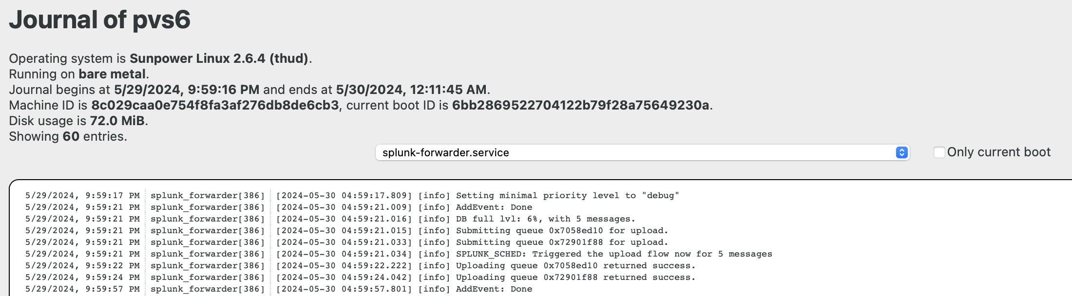
At the present time (May 2024), a bug related to this logging can cause your PVS system to stop uploading data to the SunPower “mothership.” The consequence is that the “mySunPower” app and portal stop displaying analysis information until the situation is resolved. SunPower has confirmed this issue, which is essentially a firmware bug that should be fixed. No promises have been provided for when this may happen.
One cause of this bug that has been identified and acknowledged is a situation in which, for one reason or another, the PVS is unable to successfully upload buffered (on its local file system) so-called “splunks,” causing the local storage to fill up. This condition then causes further logging to fail and also stops the regular data uploads. One known cause of this situation is an interruption in Internet connectivity for the PVS (via your WiFi or cable). If this period is long enough for the log storage to fill up, the problem occurs. If you are deploying the solutions described in this document and frequently request device list data, this can happen rather quickly because the full response content is logged.
Unfortunately, a power cycle reboot will not clear the condition, and at least one user involved in discovering this has had to have their PVS system replaced to fix the issue. I have had long periods of no reporting to Sunpower, which, at seemingly random times, resolved themselves. Once, I used the installer interface (which no longer works)) and noticed a failed firmware upgrade. I initiated that upgrade, and after that, the reporting functionality also resumed. I believe any firmware update can resolve the situation as it appears to clear the necessary storage areas, but I have not been able to confirm this positively.